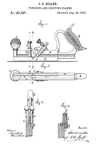
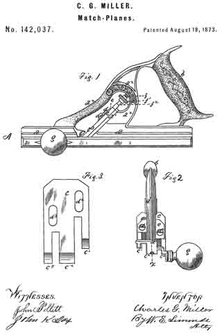
No. 165,356 – Improvement In Dado Planes (Charles G. Miller And Leonard Bailey) (1875)
UNITED STATES PATENT OFFICE.
_________________
CHARLES G. MILLER AND LEONARD BAILEY, OF NEW BRITAIN, CONNECTICUT; SAID MILLER ASSIGNOR TO SAID BAILEY.
IMPROVEMENT IN DADO-PLANES.
_________________
Specification forming part of Letters Patent No. 165,356, dated July 6, 1875; application filed February 24, 1875.
_________________
To all whom it may concern:
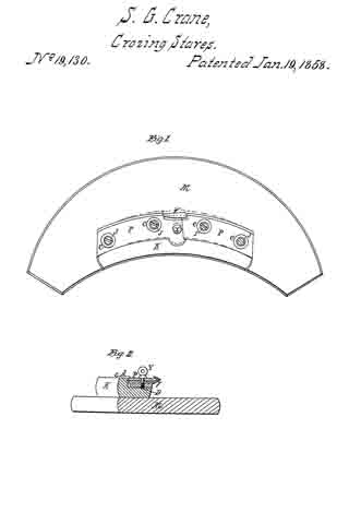
Be it known that we, CHARLES G. MILLER and LEONARD BAILEY, of New Britain, in the county of Hartford and State ot Connecticut, have invented an Improved Dado, of which the following is a specitication, reference being had to the accompanying drawings, where —
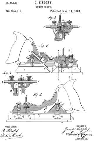
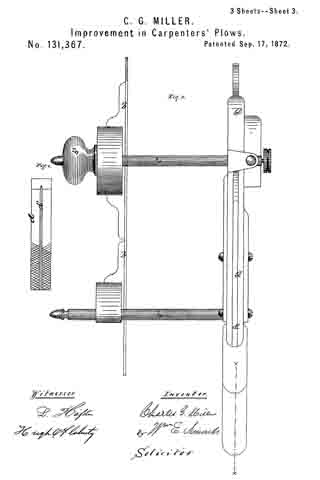
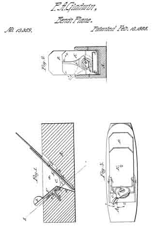
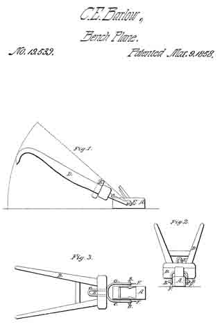
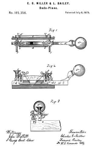
Figure 1 is a top view. Fig. 2 is a left side view. Fig. 3 is a front-end view.
The device is a joiner’s tool of that kind or class known as dados, and the features of the invention are two in number — first, a peculiar gravitating guide, which is both laterally and vertically adjustable; and, second, a depth-guide, made reversible, so that it can be used on the right or the left side ofthe body of the tool.
The parts of the tool herein shown and described are metallic, except that the knob or ball, which serves as a hand-grasp, may well be of iron.
The letter a denotes the stock or body of the tool, to the rear end of which is fixed the handle a1, having the wooden knob or hand-grasp a2. The letter b denotes the “iron,” so called; and c, the chisel or “iron ” which cuts or marks the sides of the groove, both the chisels running down the same throat. The letter d denotes a depth-gage, attached to and vertically adjustable upon the side of the body a, by means of the set screws e e, for regulating the depth of the cut. This depth gage is detachable from the left side of the body a, where it appears in the drawings, and attachable in the same manner to the right side by means of the screws e’ e’, which correspond in office and purpose to the screws e e. The letters f f denote two rods rigid on the bar g. These rods run through the sockets i i in the body a, and are set and held at a desired point by the thumb-screws h h, thus making the side guide, about to be described, laterally adjustable to and from the body a. The letter m denotes the side guide borne on the vertical rods n n, which run up through the sockets g’ g’, having vertical play therein, and thereby giving the side guide on the same vertical play, the cap-screws n’ n’ preventing the rods n n from falling down through and away from the sockets g’. The manner of using this tool is shown in Fig. 3, the letter o denoting a board with a groove, o’, cut therein, and the dado about to out another groove, the side guide m fitting against the side of the groove o’, and resting on the bottom of the groove. As the chisel of the dado cuts deeper and deeper into the wood the side guide m, remains vertically stationary, the vertical play of the rods n n permitting this. The side guide m is shown in the drawings upon the right side of the body a. It can be taken off or detached from this side and, being turned end for end, attached upon the left side of the body a in a precisely similar manner; and in such case the depth-guide d is taken off the left side of the body and, being turned end for end, attached in precisely similar manner to the right side.
We are aware that side guides are not new, nor do we mean to claim such generally, but only the peculiar combination we describe, which allows our side guide to remain stationary upon the bottom of a groove while the plane descends into the wood at another place — that is, a gravitating side guide.
We claim as our invention —
1. The combination of the stock a, rods f f bar g, sockets g’ g’, rods n n, having free play, within limits, in sockets g’, and the guide m, all substantially as described.
2. The combination of the body a with the depth-gage d and side guide on, which can be used upon either side of the body a, substantially as shown and described.
CHARLES G. MILLER.
LEONARD BAILEY.
Witnesses:
H. C. WILLIAMS,
W. H. LINSLEY.