No. 20,459 – Spokeshave (Charles H. Weston) (1858)

[paiddownloads id=”74″]20459


UNITED STATES PATENT OFFICE.

_________________

C. H. WESTON, OF NASHUA, NEW HAMPSHIRE.

SPOKESHAVE.

_________________

Specification of Letters Patent No. 20,459, dated June 1, 1858.

_________________

To all whom it may concern:

Be it known that I, C. H. WESTON, of Nashua, in the county of Hillsboro and State of New Harnpshire, have invented a new and useful Spokeshave; and I do hereby declare that the following is a full, clear, and exact description of the constriiction and operation of the same, reference being had to the accompanying drawings, forming a part of this specification, in which —

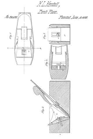
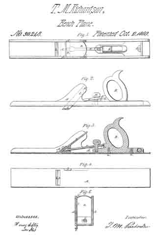
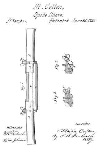
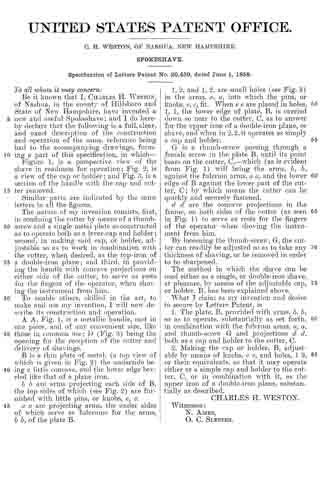
Figure 1, is a perspective view of the shave in readiness for operation, Fig. 2, is a view of the cap or holder; and Fig. 3, is a section of the handle with the cap and cutter removed.

Similar parts are indicated by the same letters in all the figures.

The nature of my invention consists, first, in confining the cutter by means of a thumb-screw and a single metal plate so constructed as to operate both as a lever-cap and holder; second, in making said cap, or holder, adjustable so as to work in combination with the cutter, when desired, as the top-iron of a double-iron plane; and third, in providing the handle with concave projections on either side of the cutter, to serve as rests for the fingers of the operator, when shoving the instrument from him.

To enable others, skilled in the art, to rnake and use my invention, I will new describe its construction and operation.

A A, Fig. 1, is a metallic handle, cast in one piece, and of any convenient size, like those in common use; D (Fig. 3) being the opening for the reception of the cutter and delivery of shavings.

B a, thin plate of metal, (a top view of which is given in Fig. 2) the underside being a little concave, and the lower edge beveled like that of a plane iron.

b b are arms projecting each side of B, the top sides of which (see Fig. 2) are furnished with little pins, or knobs, e, e.

a a are projecting arms, the under sides of which serve as fulcrums for the arms, b b, of the plate B.

1, 2, and 1, 2, are small holes (see Fig. 3) in the arms, a, a, into which the pins, or knobs, e, e, fit. When e e are placed in holes, 1, 1, the lower edge of plate, B, is carried down so near to the cutter. C, as to answer for the upper iron of a. double-iron plane, or shave, and when in 2, 2, it operates as simply a cap and holder.

G is a thumb-screw passing through a female screw in the plate B, until its point bears on the center, C, — which (as is evident from Fig. 1) will bring the arms b, b, against the fulcrum arms, a a, and the lower edge of B against the lower part of the cutter, C; by which means the cutter can be quickly and securely fastened.

d d are the concave projections in the frame, on both sides of the cutter (as seen in Fig. 1) to serve as rests for the fingers of the operator when shoving the instrument from him.

By loosening the thumb-screw, G, the cuttter can readily be adjusted so as to take any thickness of shaving, or be removed in order to be sharpened.

The method in which the shave can be used either as a single, or double-iron shave, at pleasure, by means of the adjustable cap, or holder B, has been explained above.

What I claim as my invention and desire to secure by Letters Patent, is

1. The plate, B, provided with arms, b, b so as to operate, substantially as set forth in conibination with the fulcrum arms, a, a, and thumb-screw G and projections d d, both as a cap and holder to the cutter, C.

2. Making the cap or holder, B, adjustable by means of knobs, e e, and holes, 1 2, or their equivalents, so that it may operate either as a simple cap and holder to the cutter, C, or in combination with it, as the upper iron of a double-iron plane, substantially as described.

CHARLES H. WESTON.

Winesses:
N. AMES,
O. C. SLEEPER.

No. 20,493 – Bench Plane (H. Lee Kendall) (1858)

[paiddownloads id=”75″]20493


UNITED STATES PATENT OFFICE.

_________________

H. L. KENDALL, OF BALTIMORE, MARYLAND.

BENCH-PLANE.

_________________

Specification of Letters Patent No. 20,493, dated June 8, 1858.

_________________

To all whom it may concern:

Be it known that I, H. L. KENDALL, of the city of Baltimore and State of Maryland, have invented a new and useful Improvement in Bench-Planes; and I do hereby declare that the following is a full, clear, and exact description of the construction and operation of the same, reference being had to the annexed drawing, forming part of this specification, in which —

Figure 1 is a top view of plane with bit removed. Fig. 2. is a vertical longitudinal section. Fig. 3 is a vertical section on y y. Fig. 4 is a section of plane and mouth piece, perpendicular to the face on of the mouth, taken on line z z.

Similar characters of reference in the several figures denote the same part.

The object of this invention is to furnish a ready mode of compensating for the opening of the mouth of the plane by wear of its under surface. This has been done by the insertion in the front of the mouth of a wedge to be driven downward as the mouth opened. This involved the necessity of cutting, in the front of the mouth, a grip for holding this wedge, an operation which greatly increased the labor of making the plane.

The effect of my invention is to permit the construction of plane mouths in the usual manner and at the same time provide this compensator, whereby the workmanship on the plane will be increased by the manufacture of the compensating piece alone, without the additional labor of preparing a place for its reception, the ordinary grip of the plane being made to perform the double function of securing the bit and compensator.

In the drawing G represents the ordinary grip for holding the bit. This is carried forward with an outward inclination to the inclined front surface a of the mouth in the same manner as is usual in cutting plane mouths. Into this front portion of the mouth is inserted the compensator C. This consists of a piece of hard wood with a plane under surface, and with its upper surface. inclining in opposite directions from near its middle to its extremities, as shown in Fig. 2. Its edges are inclined from its under surface at the same angle as the inclination of the faces of grip G with the surface a, as shown in Fig. 4.

The effect of this construction is to produce a close contact of surface a and lower surface of piece C, by the downward pressure of this piece, it being forced forward upon the outer surface of the grip.

A screw S serves to hold the piece C in position, though it is not absolutely necessary.

The outer face f of piece C is nearly vertical and as the piece is driven down the lower opening of the mouth will be diminished. This face moves parallel to itself and as the piece C is driven downward to compensate for wear of the mouth, the space between the bit and the face f will remain constant. This is an important result not attained by any of the compensating wedges heretofore employed. In adjusting this opening the protruding portion of compensating piece C is cut away so as to make its extremity flush with the under face of the plane.

I am aware that wedges have been inserted in plane mouths for compensating for wear on the under surface of the plane. Such therefore I do not claim. But —

What I do claim is —

The compensating piece C, formed as described, so as to be tightened by the grip and have its face f move parallel to itself as specified whereby the opening in front of the bit is not diminished by adjustment of the compensator.

In testimony whereof, I have hereunto signed my name before two subscribing witnesses.

H. LEE KENDALL.

Witnesses:
GEO. PATTEN,
JOHN S. HOLLINGSHEAD.

No. 20,615 – Device For Adjusting Plane Irons (Leonard Bailey) (1858)

[paiddownloads id=”76″]20615


UNITED STATES PATENT OFFICE.

_________________

L. BAILEY, OF WINCHESTER, MASSACHUSETTS.

DEVICE FOR ADJUSTING- PLANE-IRONS.

_________________

Specification of Letters Patent No. 20,615, dated June 22, 1858.

_________________

To all whom it may concern:

Be it known that I, LEONARD BAILEY, of Winchester, in the county of Middlesex and State of Massachusetts, have invented a new and useful Improvement in Joiners’ Planes; and I do hereby declare that the same is fully described and represented in the following specification and the accompanying drawings, of which —

Figure 1, is a top view. Fig. 2, a side elevation; and Fig. 3, a vertical, central and longitudinal section of a plane having my improvement. Fig. 4, is a top view of the friction plate and its adjuster.

The nature of my invention consists in the application of a movable friction plate and a device for adjusting or moving it to the rear side of the throat of a plane stock, and so as to support the plane iron or cutter and be a means by which it may be set or adjusted with respect to the bearing or bottom of the plane stock.

In the drawings, A, denotes the stock of which B, is the throat; C, the plane iron, the latter with its cap iron D, being held in place by a lever E, a thumb cam F, and a bearer or screw, G.

The bearer extends upward from the rear side of the throat and through slots made in the plane iron, the cap iron and the lever and its head serves as a fulcrum to the lever. A spring, H, projecting from the lever as shown in the drawings, serves to separate the thumb cam from the cap in a manner to prevent the former from being turned by the latter while it is being moved longitudinally with the plane iron.

I, is a metallic plate, which is placed fiat against the rear face a, of the throat, B, and serves to support the plane iron. This plate I, is formed with a slot, b, and a circular opening, c, the latter being for the reception of an eccentric, d, projecting from a lever, e, which turns on a fulcrum or screw, f, arranged as shown in the drawings. By turning the lever on its fulcrum in one direction the friction plate, will be raised upward in the throat. So by turning the lever in the opposite way, the plate will be depressed, the amount of movement of the friction plate depending on that of the lever. As the plane iron or cutter rests directly on and is forced down upon the friction plate, it will be moved by and with the latter and so that its cutting edge may be adjusted with great nicety with respect to its distance from or beyond the supporting face or bottom surface of the stock.

The lever, e, the eccentric, d, and the opening c, I term the adjuster, as when applied to the stock and plate, I, as described, they constitute a means of adjusting the plane iron as explained. Were the adjuster applied directly to the plane iron as it is to the friction plate, that is were we to dispense with the friction plate and insert the eccentric of the adjuster in a circular orifice made in the plane iron, it will be readily seen that but very little wear of the plane iron, such as must necessarily take place in sharpening it, or in other words, a reduction of its length, a distance equal to the eccentricity of the eccentric, would render the iron useless. By having a friction plate independent of the plane iron, the extent of grinding or reduction of the plane iron is not limited to the amount of eccentricity of the eccentric, but may be carried on to a much greater extent. Thus, the advantages of my invention will be apparent. It can be applied to most ordinary plane stocks without alteration of the plane iron, or any addition thereto, and it enables the plane iron to be adjusted with great nicety, without requiring the fastening contrivance to be first loosened.

I claim —

The combination of the movable friction plate, I, (separate from the plane iron, C,) and its adjuster or the equivalent of the latter with the throat of the plane stock and to operate the plane iron substantially as specified.
In testimony whereof, I have hereunto set my signature.

LEONARD BAILEY.

Witnesses:
R. N. EDDY,
F. P. HALE, Jr.

No. 20,855 – Spoke Shave (Leonard Bailey) (1858)

[paiddownloads id=”77″]20855


UNITED STATES PATENT OFFICE.

_________________

L. BAILEY, OF WINCHESTER, MASSACHUSETTS.

SPOKE-SHAVE.

_________________

Specification of Letters Patent No. 20,855, dated july 13, 1858.

_________________

To all whom it may concern:

Be it known that I, LEONARD BAILEY, of Winchester, in the county of Middlesex and State of Massachusetts, have invented an Improved Spoke-Shave; and I do hereby declare that the same is fully described and represented in the following specification and the accompanying drawings, of which —

Figure 1, is a top view. Fig. 2, a bottom or underside view, and Fig. 3, a vertical central and transverse section of it. Fig. 4, is a. longitudinal section taken through the retracting spring and its protecting cavity or chamber. Fig. 5, is a top view of the stock without its appliances. Fig. 6, is an end view of the spoke shave.

The nature of my invention consists in an improved spoke shave constructed with its bearing surface in front of its cutter applied to the stock by means of a lever having an adjusting screw or its equivalent or an adjusting screw and a retracting spring so applied to it as to enable the said bearing surface to be moved either toward or away from the cutting edge of the cutter in order to diminish or enlarge the chip passage as well as to vary the angular position of the said bearing surface with respect to that in rear of the cutter, whereby advantages in the operation of the instrument are attained. Also, in an application and arrangement of a protecting cavity or chamber with respect to the lever and its retracting spring.

In the drawing A, denotes the body or the stock of the spoke shave, as constructed with two handles, a, a, and a throat or recess, B, for the reception of a cutter or plane iron B’, which is arranged on the seat or bottom of the throat and is confined thereto by means of a screw, c, which passes through a slot, d, formed in the iron and screws into the stock. The head of the screw laps over the edges of the slot.

The bearing surface of the stock is composed, not only of a stationary part, d’, in rear of the cutter B’, but a movable part, e, which is arranged in front of the cutter. This movable part is made on a lever C, which is shaped as shown in the drawings, and has a journal extending from each side of it, into the adjacent side of the throat such journal being shown in dotted lines in Fig. 1. Furthermore an adjusting screw, E, screws through the back part of the lever and against the seat of the throat of the stock or such screw may pass through the lever and screw into the stock and be so applied to the lever or have such shoulders or appliances that when the screw is turned in one direction it shall tilt the rear part of the lever one way or toward the stock, and when moved in the opposite direction produce a reverse movement of the said lever.

I prefer that the adjusting screw on one side of the journal should screw through the lever and against the seat and that the part of the lever which is on the opposite side of the journals should be provided with a retracting spring I, to be fastened to it and bear on the stock. Were this spring fastened at its middle to the top of the lever and made to extend across the same in such manner as to have its ends bear on the stock, the spring would be so exposed to shavings, as they might be expelled from the throat, that they would be liable to collect between it and the lever and by so doing effect, more or less, its correct action. In order to prevent this I form within and traversely through the lever, a cavity or chamber, g, which I make of a less diameter at its middle part, than it is at its ends or as shown in Fig. 4. This cavity or chamber receives the spring I, made of a piece of round steel wire, and to fit tightly at its middle part to the middle part of the cavity while the ends of the said spring rest on the stock as shown in Figs. 1 and 6. By means of the chamber or cavity surrounding the spring, the latter is protected from shavings which during the use of the shave might rise out of the throat and get between the spring and the lever were the spring not so protected.

By means of the above described mode of changing the width of the mouth of the shave, the thickness of its cut or of the shaving made by it when in use may be regulated, a spoke shave so made being found to operate in practice to great advantage.

I claim —

1. The improved spoke shave as constructed with its bearing surface in front of its cutter, applied to the stock by means of a lever having an adjusting screw or its equivalent, or a screw and a spring applied to it so as to enable the said bearing surface to be moved with respect to the cutter, and the bearing surface in rear thereof, substantially in manner as described.

2. I also claim the arrangement and application of a projecting cavity or chamber within the lever and to the spring thereof in manner and for the purpose as hereinbefore set forth.

In testimony whereof I have hereunto set my signature.

LEONARD BAILEY

Witnesses:
R. H. EDDY,
F. P. HALE, Jr.

No. 21,311 – Securing Plane Irons To The Stocks Of Bench Planes (Leonard Bailey) (1858)

[paiddownloads id=”79″]21311


UNITED STATES PATENT OFFICE.

_________________

LEONARD BAILEY, OF WINCHESTER, MASSACHUSETTS.

METHOD OF SECURING PLANE-IRONS TO THE STOCKS OF BENCH-PLANES.

_________________

Specification of Letters Patent No. 20,311, dated August 31, 1858.

_________________

To all whom it may concern:

Be it known that I, LEONARD BAILEY, of Winchester, in the county of Middlesex and State of Massachusetts, have invented a new and useful Improvement in Hand-Planes; and I do hereby declare that the same is fully described and represented in the following speciiication and the accompanying drawings, of which —

Figure 1 denotes a top view of a smoothing plane having my invention applied to it; Fig. 2, a side elevation of it, while Fig. 3 is a central, vertical and longitudinal section of it. Fig. 4 is an underside view of the plane iron and its cap, Fig. 5 being a top view of the same. Fig. 6 is a view of the clamp lever and thumb cam thereof to be hereinafter described.

The object of my invention is to provide the plane with a ready means of fixing the plane iron or cutter in the stock or of removing the same therefrom as well as of adjusting the plane iron in the stock as circumstances may require.

In the drawings, A, exhibits the plane stock furnished with a throat, B, for the reception of the cutter or plane-iron, C, or the same and its cap iron, D. In the above mentioned drawings the cap iron, D, is exhibited as confined to the plane iron or cutter, C, by means of a screw h, extending upward from the underside of the cutter C, and through a long slot, b, formed in the said cutter as shown in Figs. 3 and 4. The bearing surface of the throat or that marked d, d, in Fig. 3, is furnished with a recess, e, for the reception of the head of the screw, h, by which the cap iron is confined to the plane iron, such recess being made of a sufficient size or diameter to allow the necessary longitudinal movements of the plane iron. Furthermore, the cap-iron as shown in the drawing, is made with a hole, f, arranged midway between its two edges and directly over the slot in the plane iron, such hole being to enable the plane iron and its cap to be passed over the head of a bearer or screw F, inserted in the plane stock and made to project from the bearing surface d, d, as shown in Fig. 3. In connection with this screw or bearer, F, a clamp lever or plate, G, is employed, it being formed as represented in the drawings and hinged or jointed at its upper end to a thumb cam, H. Moreover, the clamp lever, G, has an elongated slot, s, made through it, the said slot in one half its length being circular in form and having a diameter or width somewhat larger than the head of the bearer or screw, F, while the remainder of the slot is constructed of a width or diameter less than that of the head of the screw and sufficient to receive the shank of the screw the whole being as shown in the drawings. In consequence of the slot being so made we are enabled to slip or pass the clamp lever, G, over the head of the screw and to press the said clamp lever, G, downward in such manner as to cause the head of the bearer or screw to project beyond the sides of the slot, and constitute a fulcrum for the clamp plate when the thumb cam is turned down into the position as shown in Figs. 1 and 2. By turning the thumb cam down, we clamp or confine the plane iron in the stock, but by turning such thumb cam upward so as to bring it into the position as represented in Fig. 7 (which is another longitudinal section of the plane) we loosen the clamp lever from the bearer in such manner as to enable us either to remove it therefrom or to adjust the plane iron as circumstances may require. By turning backward the thumb cam, it will be made to so operate against the plane iron or the cap thereon as to raise the upper end of the clamp lever and force the lower end against the bearer in such manner as to cause the lower end of the clamp plate to be pressed downward upon the plane iron and secure such iron firmly upon its bearing surface, d, d. Thus it will be seen that by means of the bearer, the clamp lever and the thumb cam the plane iron may be secured in place in the throat of the plane stock or released therefrom with great facility or expedition.

By making the shank of the bearer to screw into the stock we cause the bearer to be adjustable with reference to the seat of the plane iron, and therefore we have a means of readily adapting the bearer to a plane iron of any ordinary thickness, whether provided or not with a cap iron, the adjustment of the bearer being for the purpose of causing the thumb cam and the clamp lever to be brought into the proper situations to enable them by their conjoint action as described to fasten the plane iron to the stock. If desirable, there may be two bearers, F, but I prefer to have but one, as such is quite suflicient. These bearers may be arranged near the edges and may project either from or into the stock. A single bearer, however, arranged in the middle of the seat of the plane iron and either made stationary or adjustable with respect to such seat is far preferable to more than one. Furthermore by the employment of one bearer and its arrangement at the middle of the plane iron and the clamp lever as described the lower bearing edge of the clamp lever is left free to perfectly or so perfectly adjust itself to the plane iron or the cap iron thereof as to bear thereon throughout the entire length of the edge.

I claim —

The application and arrangement of one or more bearers, F, the clamp lever, G, and the thumb cam, H, together and with respect to the top surface of the plane iron and the bearing surface or cutter seat, d, d, of the throat substantially as represented and described.

LEONARD BAILEY.

Witnesses:
R. H. EDDY,
F. P. HALE, Jr.

No. 23,678 – Bench Plane Stock (Jackson Gorham) (1859)

[paiddownloads id=”80″]23678


UNITED STATES PATENT OFFICE.

_________________

JACKSON GORHAM, OF BAIRDSTOWN, GEORGIA.

BENCH-PLANE STOCK.

_________________

Specification of Letters Patent No. 23,678, dated April 19, 1859.

_________________

To all whom it may concern:

Be it known that I, JACKSON GORHAM, of Bairdstown, in the county of Oglethorpe and State of Georgia, have invented a new and useful Improvement in Joiners’ Planes; and I do hereby declare that the following is a full, clear, and exact description of the same, reference being had to the annexed drawings, making a part of this specification, in which —

Figure 1, is a longitudinal vertical section of my invention taken in the line x, x, Fig. 2. Fig. 2, is a plan or top view of ditto.

Similar letters of reference indicate corresponding parts in the two figures.

This invention consists in having the stock of the plane formed of wood with metal sides and the front part of the wooden portion made adjustable by means of set screws, so that the “throat” may be enlarged and contracted at pleasure, as the nature of the work may require.

The invention is designed to facilitate the construction of planes and render them more perfect than those of ordinary construction.

To enable those skilled in the art to fully understand and construct my invention I will proceed to describe it.

A, represents the plane stock, which is formed of a wooden center a, a’, with a metal strip or plate b, at each side. The back part a’, of the wooden part of the stock is permanently attached to the metal plates b, b, but the front part a, is adjustable, that is to say, it is allowed to slide longitudinally between the plates b, b, and nearer to or farther from the part a’, of the central wooden portion as may be desired, — the part being secured at any desired point by set screws ax, ax.

The throat c, of the plane is formed between the parts a, a’, of the central wooden portion of the plane, the front end of the part a’, being inclined, as shown at d, and the back end of the part a, having a double inclined surface, as shown at e, f. This form of the adjoining ends of the parts a, a’, constitute the throat, and as the part a, is adjustable the throat it may be seen may be enlarged or contracted as desired.

The lower edges of the metal slides b, b, do not quite extend down to the bottom of the wooden portion a, a’, of the stock, and consequently the bottoms of the wooden portion a, a’, constitute the “sole” of the plane. The iron B, is of usual form and is fitted against the end d, of the part a’, and secured thereto by a wooden key or wedge g, which is driven behind flanches h, h, formed on the inner sides of the plates b, b, — the flanches being cast with the plates b, b.

From the above description it will be seen that the plane may be very readily constructed, much more so, than if made entirely of wood in the ordinary way. The throat c, is formed or made without difficulty and its orifice at the cutting edge of the iron B, may be contracted or enlarged as occasion may require. The plates b, b, may be of cast metal, and the central part a, a, may be of beech or other similar wood.

Having thus described my invention what I claim as new and desire to secure by Letters Patent, is,

Constructing the plane stock of a central wooden portion a, a’, secured between metal side plates b, b, provided with flanches h, h, the part a’, being permanently secured between the plates b, b, and the part a, rendered adjustable between said plates by set screws ax, ax, substantially as and for the purpose set forth.

JACKSON GORHAM.

Witnesses:
GEO.W. NEAL,
WM. O. CHENEY, Jun.

No. 23,927 – Spoke Shave (Benjamin Tolman) (1859)

[paiddownloads id=”81″]23927


UNITED STATES PATENT OFFICE.

_________________

BENJN. TOLMAN, OF PEMBROKE, MASSACHUSETTS, ASSIGNOR TO HIMSELF AND A. T. RAMSDELL, OF SAME PLACE.

SPOKE-SHAVE.

_________________

Specification of Letters Patent No. 23,927, dated May 10, 1859.

_________________

To all whom it may concern:

Be it known that I, BENJAMIN TOLMAN, of Pembroke, in the county of Plymouth and State of Massachusetts, have invented an Improved Spoke-Shave or Heel-Shave; and I do hereby declare that the same is fully described and represented in the following specification and the accompanying drawings, of which —

Figure 1, denotes a top view of it. Fig. 2, an underside view of it. Fig. 3, a front side view of it. Fig. 4, a rear side view of it. Fig. 5, a transverse and central section of it. Fig. 6, an underside view of its adjustable throat gage to be hereinafter described.

In the drawings, A, exhibits the stock or handle of the shave; B, the curved knife, while C, is the throat gage, the said knife and throat gage being constructed of metal. In spoke shaves or heel shaves as ordinarily constructed, the knife is furnished with “starts” or adjusting contrivances, which extend transversely through the handle, and cause the knife during the process of adjusting it, to be moved either toward or away from the stock. In consequence of this mode of arranging the adjustments, the knife, while the shave is being used, is very apt to be moved toward the stock or get out of place, for the great pressure employed to keep the tool in contact with the article to be shaved is borne mostly and directly by the knife and in such manner as to render the knife liable to be forced up to or toward the handle. In the construction of my improved shave I have avoided this liability of derangement of the knife. The two ears, a, a, of the knife, are not provided with starts to extend through the handle, but are formed so as to rest with broad bearings or surfaces upon flat surfaces or plates of metal, D, D, screwed or fastened lirmly to the stock, each of the said ears being provided with a slot, b, arranged transversely in it, and for the reception of one of two clamp screws, c, c, which is passed through it and screwed into the bearing plate, such clamp screw having its head projecting over the opposite sides of the slot in order that when screwed down firmly it shall confine the ear in place on the bearing piece. In connection with the said movabllie and adjustable knife, I employ an adjustable throat gage, C, which is formed as shown in the drawings, is fastened by screws f, f, to the front side of the stock. It also extends in front of the knife and between the latter and the stock, as shown in Fig. 5. The screws, f, f, pass respectively through elogated slots g, g, made in the adjustable gage C, the same being so arranged as to enable the gage C, to be moved in a direction at a right angle to that in which the knife is capable of being moved.

The object of adjusting the knife as described is to enable the cutting edge h, to be brought into a suitable position with respect to the rear edge of the bearing part, i, of the throat gage, for it will be observed that in proportion as the knife is worn down by the act of sharpening or grinding it, it will require to be moved forward. Furthermore, the object of making the throat gage adjustable is, to regulate the depth of cut or thickness of shaving to be taken by the knife.

From the above, it will be seen that the knife having been once adjusted and clamped firmly on its bearing plates cannot easily be thrown out of place while in operation, and besides this the adjustment of the distance between the knife and the throat gage can be made without disturbing the knife. As most of the pressure by which the tool is borne against an article while in the act of cutting the same, is borne by the knife, there is little or no danger of derangement of the throat gage.

I do not claim a shave made with a stationary knife and an adjustable gage; nor do I claim a shave as made with an adjustable knife and a stationary mouthpiece disposed in front of the knife, but what I do claim as my invention is —

An improved spoke shave, constructed substantially as herein before described, that is with an adjustable knife and an adjustable throat gage, arranged and applied to the stock, and so as to move with respect to one another as specined.

In testimony whereof I have hereunto set my signature this twenty eighth day of September, A. D. 1857.

BENJAMIN TOLMAN.

Witnesses:
ISAAC JOSLYN,
EVA LAMBERT.

No. 23,928 – Improved Bench Plane (William S. Loughborough) (1859)

[paiddownloads id=”82″]23928


UNITED STATES PATENT OFFICE.

_________________

W. S. LOUGHBOROUGH, OF ROCHESTER, NEW YORK.

IMPROVED BENCH-PLANE.

_________________

Specification forming part of Letters Patent No. 23,928, dated May 3, 1859.

_________________

To all whom it may concern:

Be it known that I, WM. S. LOUGHBOROUGH, of Rochester, in the county of Monroe and State of New York, have invented a new and useful Iron Fillister-Plane, the principles of which are applicable, with slight modifications, to panel-plows, match-planes, dados, rabbets, and to bench-planes; and I do hereby declare that the following is a full and exact description of its construction and operation, reference being had to the accompanying drawings, and to the letters of reference marked thereon.

Figure 1 is a side elevation. Fig. 2 is a plan of the race. Fig. 3 is a plan of the parallel fence F. Fig. 4 is an elevation ofthe reverse side of Fig. 1 without the handle, and showing the shape and position of the stop P, also of the spur M.

The nature of my invention consists, first, in the construction of an iron stock for fillisters, dados, rabbets, rnatch-planes, and panel-plows; second, in the construction of a parallel fence, F, for fillisters and match-planes; third, in the construction and arrangement of a stop, P, moving diagonally to the line of pressure upon it, the same being applicable to the dado and panchplow; fourth, in the application and arrangement of the spring-cap G, in combination with the screw 2 or any other adjustable or lined fulcrum; fifth, the combination of the adjusting-screw 1 with the bit B and spring-cap C; sixth, the application and arrangement of the spur M.

I construct the plane-stocks, as seen in Figs. 1 and 4, with an arch, N, which connects the face in front of the throat with that in the rear, and at the same time affording a cutting-edge to the bit B the full width of the face of the plane. The projection R governs the position of the bit. The screw 2 passes through the slot of the bit and into this projection, and the adjusting-screw 1 screws through the said projection and against the upper end of the bit B, so that by turning the said adjusting-screw up the edge of the bit is thrown below the face of the plane, causing it to cut a thicker shaving, and vice versa, whereby the operator is enabled to adjust the “cut” of the bit to the rnerest fraction, and in an instant.

The parallel fence F, I construct, as seen in Fig. 3, with the slots D, through which the screws Y pass, running out from the face of the fence at an angle of sixty degrees, more or less, so that when the nuts 4 and 5 are loosened to make changes one measurement only is required, for neither end can move up or back faster than the other when the screws Y are properly tilted to the slots D.

The stop P is made and arranged, as seen in Fig. 4, with the slot for the set-screw K, in this also running up diagonally from its face, so as to prevent any possibility of the downward pressure of the plane when it has worked to the desired depth from forcing the stop up, and thereby allow it to work too deep. It is kept in its proper position by the guide-pin U.

The handle H is cut to lit under the projection R, and the screw 7, Fig. 2, is put through the face of the plane and into the handle, which holds it firmly to its place.

The spur M, Figs. 2 and 4, is made of plate-steel and fitted into a dovetail seat, where it is held by the screw 6, which has a bevel or a countersunk head, one side of which is pressed against the spur when the screw is turned in.

The projections J are to allow the fence to be adjusted to the full width of the face of the plane. The rib X is to strengthen the arch N.

There may be a slip, V, of wood let into the fence F to prevent the edge of the bit from coming in contact with the iron when the bit is being taken out or replaced.

What I claim as my invention is —

1. The combination of the screw 2, (which takes effect in the projection R,) spring or yielding cap C, bit B, and screw 1, for the purpose of varying the cut of the bit, and at the same time and proportionally the space of the throat, the base of the bit B being the fulcrum upon which it swings when said changes are made, the said combination being applicable for the adjustment of the bit in all kinds of planes.

2. The adjustable parallel fence F, constructed with diagonal slots D for the set-screws Y, as and for the purpose specified, said fence being applicable to match-planes, and also the stop P, with the slot running up diagonally from the face, the set-screw K, and the guide-pin U keeping it in position, said stop being applicable to panel-plows and dados.

WM. S. LOUGHBOROUGH.

Witnesses:
CHARLES GILBERT,
RICHARD GILBERT.

No. 23,978 – Hand Plane (Simeon S. Dodge) (1859)

[paiddownloads id=”83″]23978


UNITED STATES PATENT OFFICE.

_________________

SIMEON S. DODGE, OF SUNAPEE, NEW HAMPSHIRE, ASSIGNOR TO HIMSELF, AND EDMUND BURKE, OF NEWPORT, NEW HAMPSHIRE.

HAND-PLANE.

_________________

Specification of Letters Patent No. 23,978, dated May 10, 1859.

_________________

To all whom it may concern:

Be it known that I, SIMEON S. DODGE, of Sunapee, in the county of Sullivan and State of New Hampshire, have invented a new and useful Improvement in Joiners’ Hand-Planes; and I do declare that the following is a full, clear, and exact description of the same, reference being had to the annexed drawings, making a part of this specification, in which —

Figure 1, is a prospective view of the plane with the improvements claimed by me. Fig. 2, is a sectional view of the same. Fig. 3, is a plane view of the cutter iron. Fig. 4, is a view of the curved adjustable cop-iron. Fig. 5, is a sectional view of the same. Fig. 6, is a sectional view of the top, or break iron. Fig. 7, is a plane view of the same. Fig. 8, is a sectional view of the adjustable cop iron and the break iron as adjusted for work. Fig. 9, is a view of the bolt and nuts by which the cop iron and break iron are adjusted and confined when in use.

The same letters represent corresponding parts in the various figures.

A, is the stock of the plane.

B, is the cutting iron by which the shaving is removed, and is constructed in its simplest form, as seen in Fig. 3.

C, is the cop, or break iron and is constructed substantially as seen in Figs. 6, and 7.

D, is the curved adjustable cop-iron, and is constructed as seen in Figs. 4: and 5, and is used for the purpose of adjusting the break iron C, and guiding the shaving through the mouth F, of the plane.

E, is a thumb screw which passes through the female screw e, in the break iron C, and serves to keep the latter in place, when properly adjusted for work.

G, represents one of two set screws which pass through the slots g, g, in the adjustable cop iron D, and penetrate the female screws g’, g’, in the break iron C.

H, is a bolt which passes through the stock A, in the groove h in the adjustable cop iron D.

h, is a nut on the side of the stock A, opposite to the head of the bolt H, by which the latter is confined.

In order to adjust the plane for work, the break iron C, is confined to the adjustable cop iron D, by means of the two set screws G, G, (only one of which is shown in the drawings) as seen in Fig. 8. Thus adjusted, the break iron C, and the adjustable cop iron D, are inserted in the mouth F, of the plane, in which they are confined in the right position by means of the bolt H, which passes through the groove h’, and is confined in place by the nut h. The cutter iron B, is then passed into the mouth F, and when properly set for work, is confined lirmly in place by the thumb screw E, which presses upon the upper part of the cutter iron B, bearing the lower edge of the break iron C, firmly down upon the lower portion of the cutter iron B, the bolt H, acting as a fulcrum upon which the break iron C, turns, The cutter iron B, thus adjusted for work, is seen in Fig. 2. By removing the pressure of the thumb screw E, the cutter iron B, may be easily removed, or adjusted for cutting a thicker or thinner shaving, as the work to be done may require.

It is well known that some kinds of timber to be wrought, have nearly an even and regular grain; other kinds have an uneven and irregular grain; and other kinds all knotty and shaky. Some kinds of timber are hard and tenacious; and others are soft and easily wrought. Consequently it becomes necessary that the plane should be adjusted so as to be able to work all kinds of timber with facility and without injury or waste. In working some kinds of timber a thick shaving may be taken off at a single stroke of the plane; and in working other kinds only a very thin shaving can be removed at a single stroke. In order to accommodate the break iron C, to the cutting iron B, so as to enable the latter to accomplish the various work required of it, I have out two slots g, g, in the adjustable cop D, through which the two set screws G, G, above described pass, the latter penetrating the female screws g, g, in the break iron C, as before stated. The slots g, g, permit the set screws G, G, when loosened, to pass freely up and down, thus enabling the operator to so adjust the break iron C, as to cut a thick or thin shaving, as the nature of the work may require, the adjustable cop iron D, being at the same time kept in place by the bolt H.

The advantages of my improvement, are its great simplicity, efficiency, and cheapness. The chip, or wedge, of the plane as ordinarily constructed, is entirely dispensed with. The cutting iron which, in my improved plane, is a plain piece of steel, or iron edged with steel, can be much more cheaply made; and when worn out, or broken, it can be readily removed and another substituted, without the expense of getting a new break iron each time the cutter iron is changed, or substituted. The cutting iron also can be more readily and easily removed from the stock when it requires to be sharpened, and more readily and easily adjusted for its work, than by any other device for the purpose heretofore known until my invention. It is not necessary for the operator to use a hammer about my improved plane. Thus the stock is preserved from the injury which it receives from the blows of the hammer in inserting, adjusting, confining, and removing the cutting iron, in and from it.

Having above fully described my improved hand plane, its construction, and mode of operation, what I have invented and desire to secure by Letters Patent, is —

1. The curved adjustable cop iron D, constructed and operating substantially as above described.

2. The combination of the adjustable cop iron D, with the bolt H, the set screws G, G, and the thumb screw E, and the break iron C, constructed and operating substantially as above described.

SIMEON S. DODGE.

Witnesses:
F. N. MYRIK,
I. P. OSBORN.

No. 24,335 – Securing The Bits Of Bench Planes (Charles W. Seely And Benjamin F. Locke) (1859)

[paiddownloads id=”84″]24335


UNITED STATES PATENT OFFICE.

_________________

CHAS. W. SEELY AND BENJ. F. LOCKE, OF WELLINGTON, OHIO.

MANNER OF SECURING THE BITS OF BENCH-PLANES.

_________________

Specification of Letters Patent No. 24,335, dated June 7, 1859.

_________________

To all whom it may concern:

Be it known that we, CHARLES W. SEELY and BENJAMIN F. LOCKE, of Wellington, in the county of Lorain and State of Ohio, have invented a new and Improved Plane-Bit for Planing Wood, and we do hereby declare that the following is a full and exact description thereof, reference being had to the accompanying drawings and the letters of reference marked thereon.

The nature of the invention consists in adjusting a steel bit between a cap and bed piece, which cap and bed piece are similar to the common cap and plane bit now generally used, and usually designated as the double plane bit. Our bit is manufactured entirely of steel and therefore we avoid the injurious effect produced upon steel, by the great heat to which it is necessary to subject it, to weld it upon iron; and thus we obtain a much finer and keener edged implement than can be obtained from the common method of manufacturing plane bits. Our bit also requires much less grinding than the common bit, and can be manufactured at less expense.

To enable others skilled in the art to make and use our invention, we proceed to describe its construction and operation.

This bit is manufactured of steel only, and is a thin plate varying from a sixteenth to an eighth of an inch in thickness, or thereabout, and of the usual width, with a notch in the middle of the upper end for the passage of the fastening screw. Each opposite corner of the notched end of the bit is turned down to form spurs to mesh into grooves or notches, in the bed piece, which see Figure “2” in the diagram letters “a a” which represent the steel bit and the corners.

The bed piece is represented by Fig. “1” of the diagram, is made of iron of the same width of the steel bit, and of the length of the common plane bit. The notches or grooves “a a” are for the spurs on the steel bit to mesh into, and are made about one-fourth the width of the bed piece from each edge thereof, and are exactly parallel. These and the spurs on the steel bit, are to prevent the bit from slipping up when force is applied for planing. The circular hole and notch in the bed piece is the same as in common use, and is for the entrance of the screw, by which the three pieces are fastened together as seen in Fig. “4”

The cap is made in the same manner, and like the common cap now in use, with the exception of a bar of iron just above the screw hole, and to be of the thickness of the steel bit, which is welded or riveted on the inner surface of the cap. This cross piece or bar is to prevent the cap from pressing upon the upper end of the steel bit, and thus prying apart the lower ends when the three are joined by the screw; instead of this cross piece or bar any means of making an elevation on the same surface of the cap may be used. This cap with the cross piece or bar is represented in Fig. “3” letter “a” and is also seen in Fig. “4” letter “c” The mashing of the spurs on the steel bit into the grooves on the bed piece is seen at “a” Fig. “4.”

We do not not claim broadly the interposition of a steel planing bit between a cap and bed piece, as this already has been done, but

What we claim, is —

Stopping the upper end of the interposed bit below the screw, and upsetting it, so as to catch into the cross serrations in the bed piece, as set forth.

CHARLES W. SEELY.
BENJAMIN F. LOCKE.

Witnesses:
JONATHAN ARNATT,
J. L. HUTCHINSON.

No. 24,623 – Carriage Wheel Rim Plane (Reuben Fretz) (1859)

[paiddownloads id=”85″]24623


UNITED STATES PATENT OFFICE.

_________________

REUBEN FRETZ, OF MONTVILLE TOWNSHIP, OHIO.

MACHINE FOR FINISHING THE EXTERIOR OF RIMS OF CARRIAGE-WHEELS.

_________________

Specification of Letters Patent No. 24,623, dated July 5, 1859.

_________________

To all whom it may concern:

Be it known that I, REUBEN FRETZ, of the township of Montville, in the county of Medina and State of Ohio, have invented a new and useful. Gage-Plane for Dressing the Edges of Carriage-Wheels or other Circles and Curves; and I do hereby declare that the same is described and represented in the following specification and drawings.

To enable others skilled in the art to make and use iny invention I will proceed to describe its construction and operation referring to the drawings in which the same letters indicate like parts in each of the figures.

Figure 1, is an elevation of the back side of my gage plane, Fig. 2, is a. plan or top view, Fig. 3, is a plan of the under side.

The nature of my invention for dressing the edges of carriage wheels or other circles and curves, consists in combining in the arm that gages the plane devices for varying the height of the fulcrum or center, with devices for varying its length, so as to enable the operator to dress his wheel straight or square across the edge to fit the tire. Also in making the arm which guides the plane to vibrate in the plane stock, so as to adjust and fasten it as may be desired. And in arranging some screws. to adjust the bits to suit circles of different sizes.

In the accompanying drawings A, is the top of the stock and B the bottom both of which are made in the form shown in the drawing, and fastened together by the bolts C, C. The top A, has the handle D, and pin E, fastened in it, for the operator to take hold of when he works the plane. F, is the spur iron or bit inade in the form shown in the drawing and fitted to a hole in the top A, where it is held by the wedge F’, its lower end being fitted to a score in the side of the bottom B. And to hold it firmly in the score the edges are beveled and it is fitted to a dovetailed score in the piece of metal G, fastened to the bottom B, with screws as shown in the drawing. The lower end of this spur bit is V-shaped to cut a score and sever the wood in advance of the plane bit or iron H, which is fitted to a score in the side of the bottom B, and passes up through the top A, and is fastened by the wedge H’; and to prevent the side of the stock from wearing between the bits F, and H, it is faced with a piece of metal I; and the screws J, J, are arranged to act against the bits F, and H, so as to adjust them to cut circles of different sizes. In order to enable the operator to work this plane in the arc of a circle or around the rim of a wheel, I connect it to a pin or pivot, set in the center of the circle or hub of the wheel by a compound arm which consists of the bar K, fitted to a mortise in the top A, and arranged to vibrate on the screw L, and semicircle M, which is also fastened to the top A, and there is a piece of metal N, fastened to the under side of the bar K, and provided with a set screw O, to act against the circle M, and hold the bar K, in the position desired.

The standards P, P, are fastened in the top of the bar K; and the bar Q, is fitted or provided with a slot, so as to traverse both horizontally and perpendicularly on the standards P, P; and when adjusted in the position desired, it may be fastened by the clamping screw R, which passes through both arms of the bar Q, and is arranged to traverse in slots in the arms of the bar Q, as it is traversed horizontally on the standards P, P. The end of the bar Q, is perforated at S, and bushed with a piece of metal fitted to the pivot set in the center of the circle or hub of the wheel to be dressed. The wood is cut away in front of the bit H and enlarged toward the outside of the bottom, B to let the chips escape which are cnt by the bit, H.

The plane being constructed and completed as above described and the rim of the wheel to be dressed being properly fastened to the spokes and placed in a horizontal position, and a pivot set in the hub for the end of the bar Q, to work on; and the bar Q, adjusted on the standards P, P, so as bring the plane a proper distance from the center, with its top level or the inner edge little the lowest. The plane is now worked and the edge of the wheel dressed a quarter of an inch deep all around, and then the bar Q, inust be raised a quarter of an inch on the standards P, P, when the rim may be dressed a quarter of an inch deeper; and so on until it is pressed entirely across the edge as desired.

The rims of wheels may be dressed far better and quicker and with far less labor with my plane than can be with an ordinary drawing knife. And besides it will be far less labor to fit and set the tire upon them.

I believe I have described and represented my invention, so as to enable any person skilled in the art to make and use it. I will now state what I desire to secure by Letters Patent.

1. I claim combining in the arm that gages the plane devices for varying the height of the radial arm, with the devices for varying its length so as to enable the operator to dress a wheel straight or square across the edge substantially as described.

2. I claim making the arm or bar K, which guides the plane in the arc of a circle, to vibrate in the stock, so as to adjust and fasten it in the position desired.

REUBEN FRETZ.

Witnesses:
W. L. NICHOLLS,
SIDNEY CULVER.

No. 27,983 – Bench Plane (H.C. Hunt) (1860)

[paiddownloads id=”86″]27983


UNITED STATES PATENT OFFICE.

_________________

H. C. HUNT, OF OTTUMWA, IOWA.

BENCH-PLANE.

_________________

Specification of Letters Patent No. 27,983, dated April 24, 1860.

_________________

To all whom it may concern:

Be it known that I, H. C. HUNT, of Ottumwa, in the county of Wapello and State of Iowa, have invented a new and useful Improvement in Bench-Planes; and I do hereby declare that the following is a full and exact description thereof, reference being had to the accompanying drawings, which form a part of this specification.

In the said drawings Figure 1, is a top view of my improved bench-plane; Fig. 2, a longitudinal section of the same, and Fig. 3, an edge view of the plane-bits detached from the stock.

The double bits a, b, in my improved bench-plane, are combined with each other, and with the plane-stock in the manner represented in Fig. 2, of the drawings, viz: the cutting bit b, has a central slit which passes from its upper end about two thirds the length thereof.

A metallic plate f, which is secured to the after side of the throat of the plane-stock, is of such a shape that it furnishes a metallic bearing surface for the cutting bit b, and also the requisite supporting and guiding bearings for the set-screw c. The screw shank of the set-screw c, is received into a screw-aperture in the angular nut d, which works in a slot in the throat-plate f. The cutting bit b, is combined with the front bit a, and also with the angular screw-nut d, by means of the screw g, which passes, first, through an aperture in the front bit a, then through the slit in the cutting bit, and then into the screw-aperture in the nut d. It will therefore be perceived that while the two bits a, and b, can be simultaneously moved outward or inward by turning the set-screw c, the cutting bit can also be readily adjusted so as to cause its cutting edge to project any desired distance beyond the closely embracing lower end of the front it, a.

It is well known that the cutting edge of a plane bit is more dulled and injured by the reverse movement of the plane over the surface of a board, than it is during its forward movement; which injurious action I have succeeded in entirely preventing by means of an attachment to the bits of my improved plane which I will now proceed to describe. A protecting metallic strap e, whose turned-up extremities are pivoted to the edges of the lower end of the front bit a, loosely embrace the lower end of the cutting bit b, so that when the plane is shoved forward, the said strap will swing freely upward into a notch which is formed in the plane-stock for its reception; but when a rearward movement is imparted to the plane, the said metallic strap will be drawn outward to a position that will cause it to elevate the front portion of the plane-stock a sufhcient distance above the face of the board that it may be operating upon, to prevent the cutting-bit from touching the surface of the board during the said reverse movement of the plane.

Having thus fully described my improved bench-plane, what I claim therein as new and desire to secure by Letters Patent, is —

Combining the metallic swinging strap e, with the bits of said plane substantially in the manner and for the purpose herein set forth.

The above specification of my improvement in bench-planes, signed and witnessed this 6th day of Feb., 1860.

H. C. HUNT.

Witnesses:
JAMES S. HARLAN,
ALBERT BALDWIN.

No. 28,946 – Plane Iron Sharpener (Joshua Turner) (1860)

[paiddownloads id=”87″]28946


UNITED STATES PATENT OFFICE.

_________________

J. TURNER, OF CAMBRIDGEPORT, MASSACHUSETTS, ASSIGNOR TO HIMSELF, AND F. GUILD, OF DEDHAM, MASSACHUSETTS.

PLANE-IRON SHARPENER.

_________________

Specification of Letters Patent No. 28,946, dated June 26, 1860.

_________________

To all whom it may concern:

Be it known that I, JOSHUA TURNER, of Cambridgeport, in the county of Middlesex and State of Massachusetts, have invented a new and useful Machine for Sharpening a Joiner’s Plane-Iron or other Tool of Like Nature; and I do hereby declare the same to be fully described and represented in the following specification and the accompanying drawings, of which —

Figure 1, is a top view; Fig. 2, a side elevation; Fig. 3, a rear end view, and Fig. 4, a longitudinal and central section of it.

My said machine will answer for sharpening gouges and various other tools used by turners, joiners or other artificers.

In the drawings, A exhibits a whetstone as supported by a stand or table, B, or has a wooden socket piece S, resting in or on the table. This table is furnished with two parallel rails or ways C, C, or the equivalent thereof, for supporting and guiding an arched carriage, D, which is placed thereon, as represented. Over and sustained by such carriage, D, there is a separate tool carrier or holder, E, consisting of two bars a, b, and two clamp screws, d, e. Each screw passes through the upper bar d, and screws into the lower one so that when a plane iron F, is arranged between the two bars as shown, it may be clamped to them by the screws. Each bar of the carrier has a spherical projection or ball, f, or, g, extended from it as shown in the drawings. When the carrier is applied to the carriage D, one of these balls f, g, is to rest in an adjustable cup, socket or step G, which is provided with a screw, it, to screw vertically into the carriage. By means of the screw, the bevel of the edge of the plane iron may be varied within certain limits.

In rear of the carriage and the stone holder S, of the table B, there is an adjustable stop, I, which consists of a bar, i, projecting across the two rails, C, C, and held to the table by a clamp screw, k, which extends through a long slot, l, (made in the table) and screws into a piece of metal, m, extending across the slot and arranged underneath the table as shown in Fig. 4. The said slot serves to arrest the rearward movement of the carriage so that the plane-iron while being moved backward on the whetstone may not slip off the rear end of it.

In the operation of this machine, a person after having fixed a plane iron in the holder, E, and so as to rest at the bevel of its cutting edge on the stone, bears his hands on the holder, the iron and the carriage and moves the whole backward and forward longitudinally so as to cause the iron to be sharpened by the upper surface of the stone. While this is being done the spherical projection, that may be in the cup or socket of the carriage, will enable the plane iron to conform to the stone so as to wear equally while being moved on it.

By means of the two spherical projections applied to the cutter carrier or extended from it as described and represented we are able quickly to reverse the plane iron or turn it over so as to bring its opposite face in contact with the stone. This will be found particularly useful in removing a “wire edge” from the iron or for sharpening irons or tools which have two bevels to their cutting edge. Furthermore, the spherical projection enables a gouge to be turned laterally while being sharpened.

The machine constructed in manner and to operate as described is very useful to joiners or others for rapid and accurate sharpening of their plane irons or various other cutting tools.

I claim —

1. The combination and arrangement of the separate cutter carrier and its carriage with the whetstone supporter provided with parallel ways or equivalent means of guiding the carriage, the whole being to operate together substantially as and for the purpose specified.

2. The arrangement of ball bearings on opposite sides of the cutter carrier and to operate with a socket of the carriage as specified.

3. Making the socket or step adjustable vertically for the purpose explained.

4. The combination and arrangement of an adjustable stop with the table, the cutter carrier and its carriage applied to the table and with reference to the whetstone or its supporter as specified.

JOSHUA TURNER.

Witnesses:
R. H. EDDY,
F. P. HALE, Jr.

No. 29,962 – Molding Plane (Charles Fleming) (1860)

[paiddownloads id=”88″]29962


UNITED STATES PATENT OFFICE.

_________________

CHARLES FLEMING, OF YPSILANTI, MICHIGAN.

MOLDING-PLANE.

_________________

Specification of Letters Patent No. 29,962, dated September 11, 1860.

_________________

To all whom it may concern:

Be it known that I, CHARLES FLEMING, of the city of Ypsilanti, in Washtenaw county and State of Michigan, have invented a new and useful Improvement on Tools for Making Quarter-Round and Ogee Moldings, the board to be worked standing on edge, which I call “Fleming’s self-regulating quarter-round and ogee molding tool;” and I do hereby declare that the following is a full, clear, and exact description of the construction and operation of the same, reference being had to the annexed drawings, making a part of this specification, in which the figure represents a perspective of the quartenround tool as arranged and prepared for use.

A represents the body of the quarter round tool as commonly made.

B, B, represents the key holding the iron in place.

C, C, represents the iron-and E, the face gage. Parts so far described represent the common form of this tool.

D, represents a Wood or metal gage placed upon the side of the tool as seen in the figure, Where it is attached and kept in place by the screws S, S, S.

In the ogee tool the same gage is applied in the same manner and with like effect. This gage can be applied with perfect success to any ordinary 1/4 round or ogee tool.

To use the tools, either 1/4 round or ogee, attach the gage D, as seen in the drawings. Let the iron C, C, be so ground and set in the tool that it shall out a fair shaving at the face gage E, and scarcely cut at all at the side F. Set the board on edge in the vise of the workman, and apply the tool in the ordinary way, and when the work is complete, the gage D, will arrest the further working of the tool without thought or care on the part of the workman. While with the ordinary tool, without this self-regulating gage, the tool will continue to out until the whole board is wasted, and its operation must be carefully watched by the workman, to arrest it at the proper time, and then the work will not be as perfect and uniform as with the gage D, added.

I claim —

The combination of the guide strip (D) with 1/4 round and ogee molding planes, for the purposes set forth.

CHARLES FLEMING.

Signed in presence of —
D. B. GREENE,
H. CAMP.

No. 30,071 – Spoke Shave (Samuel Leonard) (1860)

[paiddownloads id=”89″]30071


UNITED STATES PATENT OFFICE.

_________________

SAMUEL LEONARD, OF BRIDGEWATER, MASSACHUSETTS.

SPOKE-SHAVE.

_________________

Specification of Letters Patent No. 30,071, dated September 18, 1860.

_________________

To all whom it may concern:

Be it known that I, SAMUEL LEONARD, of Bridgewater, in the county of Plymouth and State of Massachusetts, have invented a new and useful Improvement in the Spoke-Shave, and do hereby declare that the same is fully described and represented in the following specification and the accompanying drawings, of which —

Figure 1 is a top view; Fig. 2, an under-side view; Fig. 3, a front elevation; Fig. 4, a rear elevation; and Fig. 5, a central and transverse section of a spokeshave containing my invention. Fig. 6 is an underside view of the stock divested of the cutter and its movable throat piece. Fig. 7 is an underside view of the throat piece and the stock as they appear when the knife is removed therefrom. Fig. 8 is a longitudinal section of the instrument taken through the springs of the throat piece.

The nature of my invention consists in an improved arrangement of the adjustable mouthpiece and its operative mechanism with respect to the stock and the cutter arranged in the stock in manner as hereinafter explained.

In the drawings, A, exhibits the stock as provided with two handles, a, a, and as constructed with a recess b, for the reception of an adjustable throat piece B, the recess and throat piece being arranged in the underside of the stock as shown in the drawings. The knife or cutter C extends longitudinally over the throat piece and in rear of its bearing face c, and is fastened at its two ends to the stock by screws, d, d. A chip throat or passage, e, is formed between the knife and the adjustable throat piece B, such chip throat or pqssage e, being made to open or have its discharging mouth at the back of the spoke shave as shown in the drawings. Near the two rearmost corners of the adjustable throat piece B, it is provided with two pivots or journals,f, f, which extend into bearings or pivot holes made in the stock and so as to enable the throat piece to be moved either toward or away from the cutting edge of the knife, its movement toward the said edge being effected by an adjusting screw, D, extending through the front part of the middle of the stock and against the throat piece, B, as shown in the drawings. Furthermore, springs, g, g, are arranged between the throat piece and the knife and near to opposite ends of the throat such springs operating to produce a counter movement of the adjustable throat.

I do not claim any improvement or any arrangement of parts as represented or as claimed in the United States Patent, No. 20855, for although I employ an adjustable bearing surface in front of the cutter and apply the same to the stock by means of a lever actuated by an adjusting screw, my invention consists in an improved arrangement and by means of it and with reference to the spoke-shave described in the said patent, I am enabled to dispense with a stock bearing surface, separate from the cutter or knife and arranged in rear thereof, and make the cutter itself or the lower surface thereof a bearing surface, and furthermore, the discharging mouth of the chip throat of my improved spoke shave is left free or has nothing in rear of it to obstruct the escape of shavings. In this way, while I gain all the advantages of the common spokeshave having no bearing in rear of its knife I also secure that of an adjustable throat and a bearing in front of the knife. Furthermore, I so arrange the space between the said throat piece and the stock, that no shaving passing into the throat can easily get between the said throat piece and the stock so as to clog the operation of the throat piece or prevent it from being moved by its adjusting screw.

I claim —

My improved arrangement of the adjustable mouthpiece and its operative mechanism with respect to the stock and the cutter
arranged in the stock as specified.

SAMUEL LEONARD.

Witnesses:
LAFAYETTE KEITH,
GEO. L. GATES.

No. 30,248 – Device For Securing Plane Bits (Theodore M. Richardson) (1860)

[paiddownloads id=”90″]30248


UNITED STATES PATENT OFFICE.

_________________

T. M. RICHARDSON, OF STOCKTON, MAINE.

DEVICE FOR SECURING PLANE-BITS.

_________________

Specification of Letters Patent No. 30,248, dated October 2, 1860.

_________________

To all whom it may concern:

Be it known that I, THEODORE M. RICHARDSON, of Stockton, in the county of Waldo and State of Maine, have invented an Improved Joiner’s Plane; and I do hereby declare that the same is fully described in the following specification and represented in the accompanying drawings, of which —

Figure 1, is a top view; Fig. 2, a side view; Fig. 3, a longitudinal section, and Fig. 4, an underside view of it. Fig. 5, exhibits a transverse section taken through the middle of the slider arranged in the side of the plane stock.

In these drawings A, denotes the stock, and, B, the handle thereof, the two being formed of metal or other suitable material and secured together by screws, a, a. The throat, b, of the plane stock is furnished with a stationary cap iron or cutter bearing, C, against the underside of which the cutter or plane iron, D, is arranged as shown in the drawings. The said plane iron is forced or clamped against the cap iron, C, by means of a wedge, E, a pitman, F, an inclined plane G, and a screw H, arranged relatively to each, the plane stock, the cutter and handle as shown in the drawings, that is to say, the wedge, E, is placed between the cutter and the base plate of the stock, while the inclined plane, G, is disposed in front of the handle and the pitman is made to extend from the inclined plane to the wedge and has the screw, H, carried through it and screwed into the front part of the base of the handle. By screwing down the said screw, the pitman will be forced down the inclined plane and by the latter will be driven forward against the wedge and thereby cause the said wedge to force the cutter or plane iron hard up against the bearing or cap iron, C. A slider, I, is arranged in the side of the plane stock and so as to slide into the recess, K, formed therein, and parallel or nearly so to the cutter. When the said slider is made to extend out of the socket or recess and beyond the lower face of the plane stock as shown in the drawings, it will serve as a guide for a workman in planing a “glue joint” or one surface at right angles to another the slider serving, in this respect, the purpose of an ordinary carpenter’s square, as its inner face, when the slider is extended shall stand at ip right angle with the underside of the stock.

In rear of the handle and in its base, I arrange a small glass spirit level L, and so as to stand transversely with respect to the plane stock, in other words at right angles with its sides, the said level being disposed as shown in Figs. 1 and 3. By this arrangement of the level it is covered and protected by the wrist of a workman while his hand may be grasping the handle, B, and thus the level is not so likely to becoine broken as would be the case were it arranged at the opposite end of the stock and in advance of the handle. My arrangement of the parts for holding the plane iron in place enables such iron to be removed and replaced with respect to the cap iron without requiring the aid of a screw driver or hammer.

I claim —

The arrangement of the clamp wedge E, the pitman, F, the inclined plane, G, and the screw, H, with the plane iron D, its cap bearing, C, and the stock A, substantially as described.

T. M. RICHARDSON.

Wtitnesses:
HENRY S. STAPLES,
ALEXANDER STAPLES, Jr.

No. 31,707 – Bevel Attachment For Bench Planes (Leonard O. Fairbanks) (1861)

[paiddownloads id=”91″]31707


UNITED STATES PATENT OFFICE.

_________________

LEONARD O. FAIRBANKS, OF NASHUA, NEW HAMPSHIRE.

BEVEL ATTACHMENT FOR BENCH-PLANES.

_________________

Specification of Letters Patent No. 31,707, dated March 19, 1861.

_________________

To all whom it may concern:

Be it known that I, LEONARD O. FAIRBANKS, of the city of Nashua, county of Hillsboro, and State of New Hampshire, have invented a new and useful Square and Bevel Attachment for Planes or other Bench-Tools; and I do declare the following is a fulland exact description thereof, reference being had to the annexed drawings.

The object of my invention is to enable persons using the ordinary bench planes to produce a square or any required bevel with certainty and despatch, Without the extraneous aid of square and bevels.

The nature of my invention consists in attaching to bench planes a clamp with an adjustable guide, and is constructed as follows: I construct a clamp A, Figure 1, of such size as will readily receive between its lugs B and binding screw C the diliierent sizes of planes, in such a manner that will secure the plane of the lugs in the square of the plane, as shown in perspective (Fig. 2). To the lugs is connected a guide plate D whose proportion is such as to secure the steadiness of a guide. At the foot of the upright A and at right angles with the face of the guide D is an adjjusting screw H which is operated by a stationary nut F. When the clamp is attached to the plane the guide plate is adjusted either at right angles with the plane stock, for the purpose of obtaining a square edge, or set at any required angle, for a bevel, by means of the adjusting nut F.

What I claim as my invention and for which I desire to secure Letters Patent is —

The attaching of an adjustable guide to the stocks of bench planes, substantially in the manner and for the purpose set forth.

LEONARD O. FAIRBANKS.

Witnesses:
O. D. MILLER,
ISAAC SPALDING.

No. 32,617 – Spokeshave (Martin Colton) (1861)

[paiddownloads id=”92″]32617


UNITED STATES PATENT OFFICE.

_________________

MARTIN COLTON, OF SARDINIA, NEW YORK.

SPOKESHAVE.

_________________

Specification of Letters Patent No. 32,617, dated June 25, 1861.

_________________

To all whom it may concern:

Be it known that I, MARTIN COLTON, of Sardinia, county of Erie, and State of New York, have invented certain new and useful Improvements in Spokeshaves; and I do hereby declare that the following is a full, clear, and exact description thereof, reference being had to the accompanying drawings, and the letters of reference rnarked thereon, in Which —

Figure I is a bottom plan of my improvement. Fig. II is a cross section on line c–d and Fig. III is a cross section on line a–b. Letters of like name and kind refer to like parts in each of the figures.

The nature of my invention relates to the connection of an adjustable cam face to the stock of the shave in such relative arrangement to the cutting knife that by its adjustment the knife will cut in any required curve.

A, represents the stock of the shave of ordinary construction. B, represents the cutting knife connected to the stock in the cornmon manner.

C, represents the adjustable cam face in length a little longer than the cutting edge of the knife — say one inch at each end — and fitting into a concave recess or chamber made in the stock to receive it. The form of the face on the side nearest the knife and connnencing at the edge of the knife and extending about two thirds of the entire circulnference of the face — is cylindrical. That part of the cam face which bears upon the work has an expanding curvature commencing at the edge of the knife and tangent to the cylindrical part. A journal is formed at each end of the cam face upon the center line of the cylindrical part. These journals turn in eyes (D) which have long shanks (E) passing through the stock and having tightening nuts (F) upon their ends. By turning these nuts the cylindrical part of the cam face llltty be drawn into the recess in the stock and held tightly in any desired position.

In consequence of the expanding curvature of the cam face by loosening the nuts If and turning it upon its journals the distance of the line of bearing upon the work from the cutting edge of the knife may be increased or diininished — increasing it will adapt it to smoothing or cutting surfaces of greater curvature and diminishing it will adapt it to surfaces of less curvature. I am thus able to adapt the shave as required by the peculiarities of the work being done and am enabled to do the work in the most perfect manner.

I claim —

The combination of the adjustable cam face C with the stock A and knife B arranged and operating for the purposes and substantially as set forth.

MARTN COLTON.

Witnesses:
R. SIMON,
SARDIS HOBART.

No. 33,240 – Improvement In Planes (Abraham S. Cross) (1861)

[paiddownloads id=”93″]33240


UNITED STATES PATENT OFFICE.

_________________

ABRAHAM S. CROSS, OF RIPON, WISCONSIN.

IMPROVEMENT IN PLANES.

_________________

Specification forming part of Letters Patent No. 33,240, dated September 10, 1861.

_________________

To all whom it may concern:

Be it known that I, ABRAHAM S. CROSS, of Ripon, in the county of Fond du Lac and State of Wisconsin, have invented certain new and useful Improvements in Joiners’ Planes; and I do hereby declare that the following is a full, clear, and exact description of the same, reference being had to the accompanying drawing, and to the letters of reference marked thereon.

In the annexed drawing, making part of this specification, A represents the body or stock of the plane, which is constructed in any of the known and usual ways. Upon each end of this stock is secured a plate 1, made of metal. These plates are both provided with circular-formed slots 3.

2 represents a bent arm, which is secured through its angular portion to the plane-stock by means of a screw 5. This arm turns upon the screw 5 as a center. When the screw is tightened the arm is made fast to the stock. One end of the arm is provided with a slot 4. A set-screw 6 passes through this slot and also through the slot 3. This screw 6 is so arranged as to allow the arm 2 to partially revolve when necessary and also to station it at any desired point. By means of the slot 4. the arm 2 is enabled to turn farther than it could otherwise do, as is clearly evident, and is thus enabled, with the help of the guide 7, to form a miter.

7 is the guide upon the end of the arm for holding the plane to its position at any angle at which it is set. This guide, together with the arm 2, may be removed at any time by simply removing the screws 5 and 6, thus making the common plane of it. The end plates with this attachment may be used upon any common joiner’s plane.

I claim —

1. The combination of the arm 2, provided with slot 4, with the slot in plate 1 for the purpose of extending the slot 3 to form a miter.

2. The combination of the guide 7, the arm 2, the slotted end plates 1, and the screws 5 and 6, when the several parts are constructed and arranged in the manner herein set forth.

ABRAHAM S. CROSS.

In presence of —
A. H. BOOTH,
E. G. GRANT.

No. 33,589 – Improvement In Spokeshaves (John Jennings Jr.) (1861)

[paiddownloads id=”94″]33589


UNITED STATES PATENT OFFICE.

_________________

JOHN JENNINGS, JR., OF NATICK, MASSACHUSETTS.

IMPROVEMENT IN SPOKESHAVES.

_________________

Specification forming part of Letters Patent No. 33,589, dated October 29, 1861.

_________________

To all whom it may concern:

Be it known that I, JOHN JENNINGS, Jr., of Natick, in the county of Middlesex and State of Massachusetts, have invented a new and useful Improvement in Heel or Spoke Shaves; and I do hereby declare the same to be fully described and represented in the following specification and the accompanying drawings, of which —

Figure 1 is a top view, Fig. 2 a bottom view, and Fig. 3 a rear side elevation of a heel or spoke shave provided with my in vention. Fig. 4 is an under side view of the stock as it appears without its knife.

In the drawings, A is the stock, and B the knife, the latter being constructed witli two tangs a, a to pass through the stock. Generally the knife-tangs pass through the stock and are secured by the friction of the wood, in which case, after a while, the reception-holes become so much worn as to render it difficult to preserve the cutting-edge of the knife at its proper or desirable distance from the throat-piece b.

In making the stock I not only construct it with two tang~holes c, c, but through each tang-hole, and so as to diverge in opposite directions from it and parallel or about so to the rear side of the stock, I run or make a saw-kerf or long slit d, the same being as represented in the figures. A screw e is passed transversely through each of the said kerfs, and is screwed into that part of the stock which is in front of the kerf. Consequently when the screw is turned up so as to force its head against the stock the wood thereof will be so sprung that a firm grasp on the adjacent knife-tang may be secured. Thus as the tang-hole may become worn by movements of the tang produced by the occasional adjustment of the knife I have a means of adjusting the tang-hole or rendering it smaller.

I do not claim the application of either wedges or metallic clamps to the stock and the tangs of the knife in order to fasten the said tangs in place in the stock. My improvement has advantages oversuch, and, besides, it materially cheapens the construction of a heel or spoke shave.

I am aware that it is not new to confine the tangs of a spokeshave in place in the stock by means of screws passing transversely into metallic projections extended from the stock, the ends of such screws bearing directly against the tangs extending longitudinally through such projections. Therefore I do not claim the broad ground of confining the tangs in the stock by means of screws; but

I claim —

Tlie improved stock as made with kerfs d, dl, arranged within it and with respect to its tang-holes c, c and to receive screws, substantially in, manner and for the purpose as specified.

JOHN JENNINGS, JR.

Witnesses:
R. H. EDDY,
F. P. HALE, Jr.