No. 53,698 – Improvement In Spokeshaves (John G. Steiger) (1866)

[paiddownloads id=”115″]53698


UNITED STATES PATENT OFFICE.

_________________

JOHN G. STEIGER, OF CLEVELAND, OHIO.

IMPROVEMENT IN SPOKESHAVES.

_________________

Specification forming part of Letters Patent No. 53,698, dated April 3, 1866.

_________________

To all whom it may concern:

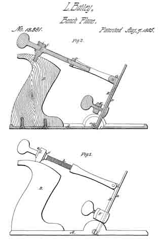
Be it known that I, J. G. STEIGER, of Cleveland, in the county of Cuyahoga and State of Ohio, have invented certain new and useful Improvements in a Box-Scraper and Draw-Shave Combined; and I do hereby declare that the following is a full and complete description of the same, reference being had to the accompanying drawings, making a part of this specification, in which —

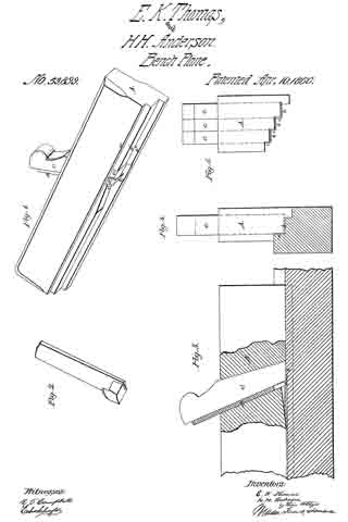
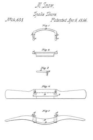
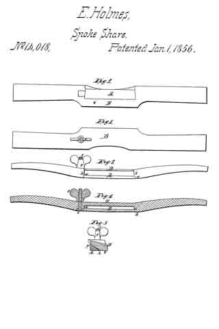
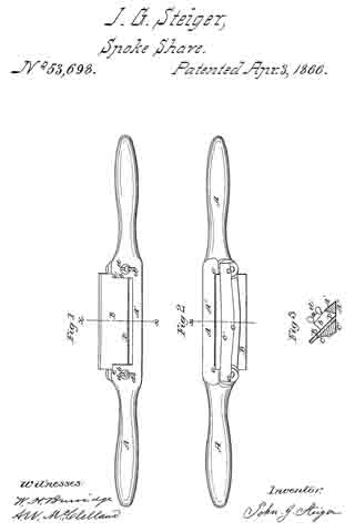
Figure 1 is a top view. Fig. 2 is a view of the under side. Fig. 3 is a transverse section in the direction of the lines x x Figs. 1 and 2.

Like letters of reference refer to like parts in the several views.

My improvement relates to a combined box-scraper and draw-shave, constructed and arranged as hereinafter described.

The draw-shave consists of an elongated metal piece, the ends A of which are shaped into handles, as represented in Figs. 1 and 2. The middle part, A’, is formed into a neck with shoulders b on each side.

B is the blade or scraper, the ends of which it into the shoulders, as shown at e.

C is a clamp fitting onto one side of the blade, holding it in place, being secured or clamped on by means of thumb – screws d, screwed through the shoulders b into the ends of the clamp, which come against one side of the shoulders. The under side, C’, of the clamp and A” of the neck, where the edge of the blade B comes through, are flat and smooth, as seen in Figs. 2 and 3.

The blade B is inclined in its position, as represented in Fig. 3, between which and the neck A’, transversely, and between the shoulders b, longitudinally, the throat D is formed, where the scrapings and shavings pass up through as it is used.

The handles A, neck A’, and shoulders b are east in one entire piece, the clamp C like-wise, so that it is very simple and economical in its construction.

The blade is made of one piece, and can be set in or out more or less, as may be desired, by simply adjusting the set-screws; or a new blade can be put in when one is worn out.

When used for a draw-shave it is of the shape represented in Figs. 1 and 2; but for a box-scraper the handles should be turned up or elevated a little, so that the hands will not come in contact with the board as it is drawn over it.

What I claim as my improvement, and desire to secure by Letters Patent, is —

The special construction of the cast handle and clamp,with the shoulders b, formed between the clamp and handle, blade B, and set-screws d, and operating substantially as described.

JOH. G. STEIGER.

Witnesses:
W. H. BURRIDGE,
FRANK ALDEN.

No. 53,899 – Planes For Making Blind Slats (Enoch K. Thomas And Hans H. Andresen) (1866)

[paiddownloads id=”116″]53899


UNITED STATES PATENT OFFICE.

_________________

ENOCH K. THOMAS, OF ROCK ISLAND, ILLINOIS, AND HANS H. ANDRESEN, OF DAVENPORT, IOWA.

IMPROVEMENT IN PLANES FOR MAKING BLIND-SLATS.

_________________

Specification forming part of Letters Patent No. 53,899, dated April 10, 1866.

_________________

To all whom it may concern:

Be it known that I, ENOCH K. THOMAS, of Rock Island, Rock Island county, and State of Illinois, and HANS HEINRICH ANDRESEN, of Davenport, Scott county, State of Iowa, have invented a new and useful Plane for Making Window-Shade Slats; and we do hereby declare that the following is a full, clear, and exact description thereof, reference being had to the accompanying drawings, making a part of this specification, in which —

Figure 1 is a perspective view of a single-iron slat-plane. Fig. 2 is a perspective view of the cutter or plane-iron detached from the plane-stock. Fig. 3 is a sectional view, showing the mode of cutting slats from a piece of wood. Fig. 4 is a front end view of the single iron plane. Fig. 5 is a front end view of a plane-stock which is adapted for receiving three cutters.

Similar letters of reference indicate corresponding parts in the several figures.

The object of this invention is to produce slats for wooden window-shades of a uniform thickness and width by means of a plane which is so constructed that the slats pass freely through the plane-iron between the sole of the plane-stock and its bottom cutter without liability of becoming broken or otherwise injured, as will be hereinafter described.

To enable others skilled in the art to understand Our invention, we will describe its construction and operation.

The plane which we have represented in Figs. 1, 2, 3, and 4 of the drawings is intended for cutting one slat at a time from a piece of wood. The sole of this plane has three steps, a a’ a”. The intermediate step, a, is equal in width to the width of the slats which are produced, and the vertical surface of the step a2 is intended to form a side guide for the plane-stock in its forward movements over the piece of wood from which the strips or slats are cut.

The cutter or plane-iron B has a cutting-lip, b, on its lower end and a cutting-lip, c, formed on one side — that side which is nearest the step a. This plane-iron has an opening, d, through it, which should be equal in width to the width of the slats that are cut, so that as the slats that are severed from the piece of wood by the horizontal and vertical cutting-lips b c these slats will pass freely through the plane-iron without being materially bent out of a straight line, as shown in Fig. 3.

The plane-iron B is secured at the required pitch in its stock A by means of a wedge, C, in the usual manner of securing common plane-irons into their stocks, and the cutting-lip b projects below the sole of the stock a distance which is equal to the thickness desired for the slats.

It will be necessary to form a depression, e, just in rear of the cutter lf, so as to allow of the slats rising over this cutter; but as this cutter can be made quite thin, it will not be necessary to form much of a depression in the sole of the stock.

To obviate a gouging action of the cutting-lip b, which would cause the plane to work very hard and produce slats of an uniform thickness, the space between the cutting-edge of said lip and the lower end of the wedge C should not be greater than the required thickness ofthe slats. The space back of this point for a short distance may be increased, as above mentioned.

It will be seen from the above description of our plane or slat-cutter that the slat is held firmly down upon the surface of the piece of wood during the operation of producing it, and that the only elevation of the slat from such surface takes place at the cutter b, which must pass under the slat; but while this is the case the slat which is being cut will he held down in rear of said cutter, so that it cannot be broken or split.

We do not confine our invention to a single-iron plane for cutting or producing slats, as the stock may be adapted for receiving two, three, or more cutters, arranged as shown in Fig. 5, so that a number of slats can be cut at each forward movement of the plane over the piece of stuff.

It is obvious that this plane may be secured to a bench-vise or to any other object and the stuff moved over it instead of moving the plane by hand over the fixed stuff ; or, if desirable, the plane or the stuff from which the slats are cut may be moved by machinery without changing the principle of our invention. One great advantage of our invention is that we can cut slats from the side or edge of a board or log without the necessity of resawing and previously dressing the stuff, and this can be done with stuff of any thickness or width.

Were not our cutter provided with the two cutting-edges described, the splints or slats could not be cut from a bolt or plank of a greater thickness than the length of the cutting-edge of the cutter or plane-iron. This will be evident from an inspection of the drawings illustrating our mode of cutting strips or splints from a large bolt or log.

By arranging a series of cutters on a plane-stock, stepped as shown, we can, after having cut a series of splints from the bolt, bring two cutters into use, and after we have cut another series of splints by each of the two cutters we can bring into use a third cutter in connection with the two which are already brought into use, and so on, according to the number of steps and cutters provided on the plane-stock. To bring the different cutters into use a channel in the wood must be made tbr a succeeding cutter by a preceding cutter, as must be evident. Thus by our invention a series of splints may be cut at one time from a bolt which is of much greater thickness than the length of the edge of either of the cutters after channels adapted for the respective cutters are cut in the bolt.

Having thus described our invention, what we claim as new, and desire to secure by Letters Patent, is —

1. The construction of a cutter for producing slats with two cutting-edges and an opening through the shank of the cutter for the passage ofthe slats, substantially as described.

2. The combination of one or more slat-cutters, constructed substantially as described, with a plane-stock having its sole stepped substantially as set forth.

ENOCH K. THOMAS.
HANS HEINRICH ANDRESEN.

Witnesses:
HANS ARBAHR,
HANS KÜHAER.

No. 17,657 – Bench Plane (Thomas D. Worrall) (1857)

[paiddownloads id=”47″]17657


UNITED STATES PATENT OFFICE.

_________________

THOMAS D. WORRALL, OF LOWELL, MASSACHUSETTS, ASSIGNOR TO HIMSELF AND THOMAS F. CALDICOTT, ASSIGNORS TO THOMAS F. CALDICOTT, OF CHARLESTOWN, MASSACHUSETTS.

PLANE FOR FINISHING GROOVES IN PATTERNS &c.

_________________

Specification of Letters Patent No. 17,657, dated June 23, 1857.

_________________

To all whom it may concern:

Be it known that I, THOMAS D. WORRALL, of Lowell, in the county of Middlesex and State of Massachusetts, have invented an Improved Bench Plane or Jointer; and I do hereby declare that the same is fully described and represented in the following specification and the accompanying drawings, of which —

Figure 1 is a top view of the same. Fig 2 a side elevation o it. Fig. 3 a vertical, central, and longitudinal section of it. Fig. 4 a horizontal section of its cutter holder and clamp.

In these drawings A denotes the body or stock of the plane as made of wood and having a handle B projecting upward from it, such part A generally being about one-half or less than one-half the thickness of stocks for bench planes or jointers as ordinarily made. The said stock is provided with a separate metallic cutter holder C, which is placed on its top and fastened to it by means of screws as seen at a, a. This cutter holder formed as shown in the drawings, is furnished with a slide clamp D, made so as to embrace a dovetailed projection ln, extending from the rear side of the cutter or plane iron E, as shown in the drawings. Such slide is provided with a slot f, for the reception of wedges F, G, which act against one another, the rear end of the slot and a shoulder c formed in the cutter holder. By driving up these wedges the cutter is drawn firmly down upon its seat d, formed in the holder and does not depend on the wood of the plane iron to enable it to be held in place.

By my construction of the plane important advantages are gained. It may be made lighter than ordinary planes of the kind ; its cutter is more firmly held in position ; its devices for clamping the cutter are compact and disposed in convenient positions for the carpenter to operate them as occasion may require. Furthermore, they are well protected both by the handle and the cutter so as not to be liable to be disturbed or disarranged except as occasion may require.

What I claim is —

The improved manufacture of carpenter’s bench plane or jointer as made with its handle, its wooden stock to which said handle is atlixed, and a separate metallic cutter holder, and cutter clamping devices arranged together substantially as specified.
In testimony whereof I have hereunto set my signature.

THOS. D. WORRALL.

Witnesses:
J. C. DOWNING,
JOHN E. CRANE.

No. 16,889 – Carpenter’s Plane (M.B. Tidey) (1857)

[paiddownloads id=”38″]16889


UNITED STATES PATENT OFFICE.

_________________

M. B. TIDEY, OF ITHACA, NEW YORK.

CARPENTER’S PLANE.

_________________

Specification of Letters Patent No. 16,889, dated DMarch 24, 1857.

_________________

To all whom it may concern:

Be it known that I, M. B. TIDEY, of Ithaca, in the county of Tompkins and State of New York, have invented a new and Improved Mode of Constructing Bench-Planes; and I do hereby declare that the following is a full and clear description of the same, reference being had to the accompanying drawings, forming part of this specification, in which —

Figure 1 is a View of the cavity or throat opening of the plane stock as constructed for the reception of the bit-case. Fig. 2 is a reverse view of the same and Fig. 3 is a longitudinal sectional view thereof. Fig. 4; is a bit-case to be applied to said cavity and Fig. 5 is a view of the lower extremity thereof. Fig. 6 is the same as Fig. 1 with the bit-case applied, and Fig. 7 is a reverse view of the same. Fig. 8 is a view of the plane complete as invented and constructed by me.

Similar letters of reference indicate corresponding parts in these several figures.

The object of this invention is, first to simplify the manufacturing of planes; second to render them more durable; third to retain a uniform mouth; fourth to obviate their clogging and fifth the retention of the essential part of the plane when the stock is worn out.

The following description will enable those skilled in the art to make and use my invention.

The mode of my invention consists in the construction of planes of wood and in the usual way with the exception of the cavity or throat opening which is essentially different as will be seen hereafter.

I construct in the plane stock a cavity of uniform width as denoted by lines a, Figs. 1, 2, 6, 7, and 8, which terminates longitudinally at lines 5, Figs. 1, 2, 3, 6, 7, and 8. Fig. 1 is an upper view of said cavity showing also the adjustable screw B with supporting nut C and screw holes f, f, also finishing cuts c, c. Fig. 2 is a reverse view of the same showing the face of the plane. The lines F, F, F, F, Fig. 3, represents the back face and the lower part of the front face of the cavity or throat opening and are to be made parallel with each other or nearly so, the object of which is to prevent any space or opening at point D, Fig. 7, by drawing up the bit-case for the purpose of refacing the plane. In the cavity as thus constructed I apply the metallic bit-case (Fig. 4) as seen at A, Fig. 6, which is secured thereto by screws d d through slots e, e, entering nut f, said nut being a rod of iron passing through the plane stock for that purpose. The bit-case passes through the stock, its lower extremity constituting a section of the plane’s face being provided with a mouth q and other formations necessary to the reception of the bit and its means of fastening thereto. The bit-case I arrange so as to be adjusted according to the wear or diminution of the plane’s face, for which purpose I throw the upper extremity of the case back making a projection at right angles with its bed A, which is provided with recess g, which is received by groove h, of adjustable screw B, by the operation of which the bit-case may be set at pleasure, slots e e, Figs. 4 and 6, admitting its passage under screw heads d, d, when loosened.

What I claim as my invention and desire to secure by Letters Patent is:

The application to the cavity of the plane stock of a metallic bit-case and so applying it that its lower extremity shall constitute a part of the plane’s face constructed and operated substantially for the purpose and in the way set forth.

M. B. TIDEY.

Witnesses:
WM. ANGLE,
WM. F. PECK.

No. 16,805 – Carpenter’s Plane (Oldin Nichols) (1857)

[paiddownloads id=”37″]16805


UNITED STATES PATENT OFFICE.

_________________

OLDIN NICHOLS, OF LOWELL, MASSACHUSETTS.

CARPENTER’S PLANE.

_________________

Specification of Letters Patent No. 16,805, dated March 10, 1857.

_________________

To all whom it may concern:

Be it known that I, OLDIN NICHOLS, of Lowell, in the county of Middlesex and Commonwealth of Massachusetts, have invented a useful and novel Changeable Multiform Plane; and I hereby declare that the following specification, in connection with the accompanying drawings and references thereon, constitute, embody, and designate a clear, lucid, and exact description of the construction, application, and use of the same.

In explanation of the accompanying drawings and for reference thereto, Figure 1, denotes a plan or top view of the plane stock with the iron, and handle secured thereto, the handle being secured to the top of the plane. Fig. 2, denotes a side elevation of the same. Fig. 3, is a longitudinal and vertical section of it, on line A, B, Fig. 1. Fig. 4, is a plan of my plane with the handle attached, in its lowest position. Fig. 5, denotes a side elevation of the same. Fig. 6, is a longitudinal and vertical section of the same on line C, D, Fig. 4. Fig. 7 is a plan removed from the plane stock, of the cam shafts H and L, for holding both the plane iron and handle to the plane stock, and with the wrench for operating this cam, and for screwing the cap to the plane iron connected to, or placed on the cam shaft. Fig. 8, is a plan of this wrench. Fig. 9, denotes a plan of the plane iron C removed from the plane stock, with a section of the hook headed bolt E therein showing this bolt slabbed on each side to prevent turning when the cap D, is screwed to the iron C by the wrench I. Fig. 10, is a section of the plane stock A with a plate seen at gf intervening between the hook E and cam H.

Invention — The nature of my invention consists in firmly connecting the plane iron to the cap by means of a hook headed bolt and two nuts thereon, and the arrangement of a cam shaft to act on this hook by means of a wrench or its equivalent in such manner as to securely hold the plane iron to the stock, and the intermediation of a plate between the surface of the cam shaft and hook, which would otherwise come together to hold the plane iron to the stock, and the application of substantially the same arrangement to the handle whereby one handle will answer for any number of planes or molding tools, and the variable position of this handle which can be changed on the same, to be nearly as low as the face of the plane, to operate it with the greatest ease or in securing it to the top of the plane for planing floors or any desired work, all as hereinafter set forth.

Construction — To enable persons which are efficiently skilled in the art to which my invention appertains, to construct and carry out the same, I will describe it as follows:

I construct a plane stock as seen at A, in Figs. 1, 2, 3, 4, 5, 6, and 10, of the drawing, I then construct the plane iron seen at C Figs. 1, 2, 3, 4, 5, 6, 9, and 10, and the cap seen at D, same figures, and secure them together by a hook headed bolt seen at E Figs. 1, 2, 3, 6, 9 and 10, on which is placed two nuts, one top of the cap seen at F, Figs. 1, 3, 4, 6, and 10, and the other one under the plane iron seen at G Figs. 3, 6 and 10, these nuts are both properly threaded to the bolt E, the top one F, is to firmly hold the cap D to the iron C, and the lower one G, is to adjust the position of the surface or face a, Figs. 3, 6, and 10, of the hook headed bolt E, any desired distance from the iron C, in order to be in the proper position to be acted upon to hold the plane iron to the stock by the cam seen at H, Figs. 1, 2, 3, 4, 5, 6, 7, 3, and 10, which is fitted to the plane stock A, by first forming a hole therein for this cam shaft to freely turn in, the cam shaft H is constructed by turning an iron arbor round and smooth, and forming one of its ends square, on which to place the wrench I Figs. 7 and 8, so as to turn this cam shaft, to tighten and hold the iron to the stock by bringing the surface e, Figs. 3, 6, and 10, of this shaft H in contact with, and against the surface a, of the hook headed bolt E.

A portion of the cam shaft H, is removed leaving a vacant place seen at i, Figs. 3, 6, 7, and 10, so that by turning this cam shaft around so as to bring this vacant place i opposite or nearest the face a, of the hook E, the plane iron will be liberated so that it may be removed from the plane stock, for sharpening or any desired purpose.

It is designed to turn the cam shaft H, so as to bring its surface e, against the surface a, of the hook, in the position seen at Figs. 3, and 6, and 10, in order to hold the plane iron sufliciently firm to the plane stock, while this iron can be driven down to take a rank shaving, or driven up to take a lighter shaving as may be desired by the operator, without altering the tension of the iron to the plane stock.

A plan of the cam shaft H is shown in Fig. 7, disconnected from the plane stock, to better illustrate the part removed leaving a vacant place seen at i, for liberating the plane iron from the stock; an edge view of the wrench I, is also shown connected to this shaft H, in Fig. 7, and a plan of it is shown at Fig. 8, the large end J being fitted to turn either of the nuts F or G, for the purposes before stated i, e, for holding the cap D, to the plane iron C, and for adjusting the hook surface a, of the bolt, to be correctly operated upon by the cam shaft H, to hold the plane iron firmly to the stock.

At Fig. 10 is seen a plate g, held to the stock A, by the screw y, this plate intervenes between the surface e, of the cam shaft H, and the surface a, of the hook E, to prevent wear of these surfaces, and to prevent the plane iron from sliding, or moving when it is tightened to the stock. Single plane irons can be secured to the plane stock in precisely the same manner every way as the double iron; the hook headed bolt may be as much shorter for the single iron than it is in the double one, as the thickness of the cap D, which will be readily understood.

I construct one plane handle seen at B Figs. 1, 2, 3, 4, 5 and 6, so as to answer for a whole set of planes, or for any number of planes and molding tools by shaping its front edge as seen at n, and m Figs. Q, 3, 5 and 6, so that the surface n, of the handle B can be placed on the top or higher surface of the plane A, as seen at Figs. 2 and 3, the hook K Figs. 2 and 3, 5 and 6, swinging free on the pin , Figs. 3, 4, 5 and 6, in the slot P, Figs. 3 and 6, the surface k, of the hook K, is operated upon (after being placed in the mortise M) by the surface h, of the cam shaft L, to hold the plane handle firmly to the stock, by turning the cam shaft L with the same wrench I, that is used to operate the cam shaft H, and nuts F and G.

The elevated position of the plane handle is designed for using the plane to finish floors of vessels or buildings and for smoothing or finishing in corners or places diflicult of approach, the distance from the center of the pin Q, in the plane handle, to the center of the cam shaft L, in the plane stock is the same whether the handle is in the elevated or lower position.

The handle B, can be instantly removed from the plane stock A, Figs. 1, 2, and 3, or equally well from any molding tool stock by placing the wrench I upon the square part of the cam shaft L and turning it back so as to bring the vacant or open part j, of the cam shaft L, nearest to the surface k, of the hook K, when the handle will be liberated and it can then be placed in the lowest position as seen at Figs. 4, 5, and 6, by placing the hook K into the mortise N, and the surface k, so that it can be operated upon by the surface h, of the cam shaft L, to firmly hold the handle B, in the lowest position seen at Figs. 5 and 6, which is the best for the easy working of the plane, by reason of the hand of the operator being thus in the lowest position possible when operating the plane and of course the hand will thus operate the plane in nearly a direct line with its face. The advantages are very great in this changeability of handle on the same plane from a higher to a lower, or from a lower to a higher position to work the plane with the great-est ease, or for convenience in working the plane in low places, or unapproachable places for the body, while the arms and hands can reach to work the plane if the handle be secured to the stock in the elevated position as seen at Figs. 1, 2, and 3, and another important advantage is my arrangement, whereby the handle can be applied to any number of either planes or molding tools, or both, thus saving much expense in first constructing the tools, and then in packing them, besides the advantage of change of position of the handle on the same plane, as above stated.

Use — In using my invention of plane, the cap D, has first to be secured to the plane iron, if the iron be a double one, by the fork J, of the wrench I, applied to the nut F, then it is placed in the plane stock A, in position to cut in the usual manner, the cam shaft H being of course turned so that its recess i, is next the surface a, of the hook-headed bolt E, then this cam shaft H, is turned so as to bring the surface e against, and in contact with the surface a, of the hook E, which will firmly hold the plane iron to the stock. When the round surface e, of the cam shaft H, is brought in contact with the surface a, of the hook E, no farther pressure will be had, if the cam shaft H, be turned farther because this surface e, is the round part of the cam shaft H, and this arrangement will allow the operator to either set, or adjust the plane iron (to give the thickness of shaving) with a hammer, or with the cam shaft H and wrench I, as he may wish.

The plate g, Fig. 10, intervenes between the surface a, of the hook E, and the surface e, of the cam shaft H, and prevents wear, and also prevents the plane iron from sliding by the friction on the hook E, caused by turning the cam shaft against it to tighten the iron to the plane stock.

For using the plane or molding tool, upon bench work the lower position of handle, seen in Figs. 4, 5, and 6, is the desirable one, as the plane will work much easier by the hand of the operator at this low point of the plane, but if floors of vessels or buildings, or other like surfaces are to be planed which are low and more difficult of access than bench work, then the higher position of the handle is desirable, as seen in Figs. 1, 2 and 3. The change of handle from one position to another is effected simply by turning the cam shaft L, back with the wrench I, sufliciently to liberate the hook handle K, then remove this handle and place it in the lower position, with the hook K, so that the cam shaft L, can be turned by the wrench I to tighten the plane handle in the desired position.

What I claim, is —

1. Connecting the cap D, to the plane iron C, by the hook headed bolt E with two nuts F, and G, thereon to hold them together, and then securing the iron to the plane stock A, by a cam shaft H operating upon this same hook headed bolt, which is so adjustable as to be lengthened or shortened that any desired pressure may always be had, to firmly hold the iron to the stock, by turning the cam shaft, and still allow the plane iron to be moved in or out of the plane to cut a thick or thin shaving, without farther tightening or loosening it, these parts being arranged and operated essentially in the manner and for the purposes fully set forth.

2. I also claim the plate g, secured to the plane stock, and intervening between the surface a, of the hook E, and the surface e, of the cam shaft H, to prevent wear of the hook and cam, and also to prevent the hook E, and plane iron C from sliding back when the cam shaft H, is turned to tighten the iron to the plane stock, essentially in the manner and for the purposes fully set forth.

3. I also claim the application of one single handle B, to answer for, and be secured to a whole set or any number of plane stocks, either in the lower or elevated position, and changeable from one position to another or from one plane to another, instantly and be secured firmly thereto by means of the hook K, and cam L, or their mechanical equivalents arranged and operated essentially in the manner and for the purposes fully set forth.

OLDIN NICHOLS.

Witnesses:
JOHN S. JACQUES,
E. W. SCOTT.

No. 16,569 – Joiner’s Plane (J.F. Palmer) (1857)

[paiddownloads id=”36″]16569


UNITED STATES PATENT OFFICE.

_________________

J. F. PALMER, OF AUBURN, NEW YORK, ASSIGNOR TO S. W. PALMER, OF DETROIT, MICHIGAN.

JOINER’S PLANE.

_________________

Specification of Letters Patent No. 16,569, dated February 3, 1857.

_________________

To all whom it may concern:

Be it known that I, J. F. PALMER, of Auburn, in the county of Cayuga and State of New York, have invented a. new and useful Improvement in Joiners’ Planes; and I do hereby declare that the following is a full, clear, and exact description of the same, reference being had to the annexed drawing, making a part of this specification, said drawing being a longitudinal vertical section of my improvement.

My invention consists in the peculiar means employed for adjusting the plane iron, as will be hereinafter fully shown and described, whereby the plane iron may be set with the greatest facility and also be raised free from the work as the plane is drawn back so that the cutting edge of the iron is not impaired thereby.

To enable those skilled in the art to fully understand and construct my invention, I will proceed to describe it.

A represents the plane stock which is constructed of wood and in the usual manner. B is the opening or throat in the plane, and C is a metal plate which is screwed to the back side of the opening or throat, the lower edge of the said plate being beveled and made flush with the bottom or face of the stock. The upper end of the plate is also flush with the upper surface of the stock. The plate C has an oblong recess (a) made in it to receive a spiral spring (b) and also has four guide slots made in it to receive pins (d) which are attached to the back of a plate D which is fitted over the plate C, the plate D being a trifle shorter than the plate C. The plate D has a projection or lip (e) on its back side, said projection or lip fitting over the spring (b) in the recess (a) of the plate C. The projection or lip (e) is notched, or it may be formed of two parts to allow a screw rod E to pass through it. The upper end of the screw rod has a small thumb wheel (f) upon it, and a groove or recess (g) is made circumferentially in the upper part of said rod to receive a fork (h) which is attached to the back side of the plane iron E’. The lower part of the screw rod has a nut F upon it which leans upon the projection or lip (e) on the plate D, and this nut has a screw (i)attached to it, said screw passing through a hole (j) in the plate D, and through a slot (j’) in the plane iron E’, and having a thumb nut (k) on its outer end. The lower part of the plane iron E’ has a cover iron G attached to it.

The upper edge of the nut F is beveled as plainly shown in the drawing, and a rod H is fitted longitudinally in the stock A, said rod having a vertical plate I attached to its back end, the plate I being at the back side of the tote or handle J. The front end of the rod H has a fork (l) formed on it, and when the rod H is pressed forward, it passes through an opening in the plate C and bears upon the upper nut F — a spiral spring (m) is placed upon the rod H, said spring keeping the fork free from the nut F.

From the above description will be seen that by turning the screw rod E, the plane iron E’ may be raised or lowered so as to give it the required “set,” and the plane iron is firmly secured in position or prevented from turning casually. The plate D is connected with the plate C by a guide pin so as to regulate the length of vibration of the plate D and plane iron E’, which are forced downward as the plane is shoved forward by pressing the palm of the hand against the plate I, the rod H being shoved forward thereby and the fork (l) bearing or pressing down the nut F, and consequently the plate D and plane iron E’, said plate and plane iron being kept up above the work or board being planed by means of the spring (b).

By the above improvement the plane iron may not only be set with facility but it is kept up from the work as the plane is drawn backward and consequently the cutting edge of the iron E’ is prevented from being rounded and rendered dull. The plane irons of ordinary planes are soon deprived of their sharp edges in consequence of being drawn backward over the work.

Having thus described my invention, what I claim as new and desire to secure by Letters Patent, is,

The two plates C, D, and plane iron E’ arranged relatively with each other as shown and used in connection with the screw rod E, and rod H as herein described and for purpose set forth.

J. F. PALMER.

Witnesses:
HORACE T. COOK,
C. H. JENKIN.

No. 16,412 – Adjusting The Size Of The Mouth In Planes (Thomas J. Tolman) (1857)

[paiddownloads id=”35″]16412


UNITED STATES PATENT OFFICE.

_________________

THOMAS J. TOLMAN, OF SOUTH SCITUATE, MASSACHUSETTS.

METHOD OF ADJUSTING THE SIZE OF TI-IE MOUTH IN PLANES.

_________________

Specification of Letters Patent No. 16,412, dated January 13, 1857.

_________________

To all whom it may concern:

Be it known that I, THOMAS J. TOLMAN, of South Scituate, in the county of Plymouth and Commonwealth of Massachusetts, have invented a new and Improved Attachment to Rabbet-Planes; and I do hereby declare that the drawing forwarded and accompanying this petition is a full and exact representation of the same.

The nature of my invention consists in providing on the face of said plane an attachment of boxwood the fore part of which, or that part thereof which is forward of the plane iron being movable by means of a screw attachment, A and key B, thereby regulating with ease and certainty the size of the mouth and the working of the plane, and producing much smoother and nicer work — and to regulate the size of the mouth it is only necessary to start said key and screw. The durability of the plane is also increased four-fold.

What I claim as my invention and desire to secure by Letters Patent, is —

The application to the common plane of the screw attachment and key, through the same, thereby regulating the mouth and greatly increasing its value.

In witness whereof I have hereunto subscribed my name the seventeenth day of December, eighteen hundred and fifty-six.

THOMAS J. TOLMAN.

In presence of —

ALEXANDER WOOD,
EDWARD F. WOOD.

No. 16,309 – Adjusting Bits Of Carpenter’s Planes (Thomas D. Worrall) (1856)

[paiddownloads id=”34″]16309


UNITED STATES PATENT OFFICE.

_________________

THOMAS D. WORRALL, OF LOWELL, MASSACHUSETTS.

ADJUSTING THE BITS OF CARPENTERS’ PLANES.

_________________

Specification of Letters Patent No. 16,309, dated December 23, 1856.

_________________

To all whom it may concern:

Be it known that I, THOMAS D. WORRALL, of Lowell, in the county of Middlesex and State of Massachusetts, have invented certain new and useful Improvements in Carpenters’ Bench-Planes; and I do hereby declare that the same is fully described and represented in the following specification and the accompanying drawings, of which —

Figure 1, is a top view. Fig. 9, a side elevation. Fig. 3, a vertical and longitudinal section, and Fig. 4, a horizontal and longitudinal section of one of my improved bench planes, the latter section being taken through the pinion gear by which the plane-iron or cutter may be elevated or depressed within the throat of the stock.

In the said drawings, A, denotes the stock, B, the cutter or plane-iron, and, C, the throat of the stock.

In order to hold the plane-iron within the stock, I employ a clamp or piece of metal, D, made so as to embrace a dovetailed rack bar E, fixed to the rear side of the cutter, B, as shown in Figs. 3 and 4. The clamp is arranged within a cavity or recess, F, formed in the stock and leading out of the rear side of the throat thereof. A female screw, a, is made through the rear part of the clamp and so as to receive a male screw cut on the end of a long rod, G, which extends backward through the stock and has a hexagonal head, c, as shown in the drawings. The rack, E, is provided with teeth on its rear side to cooperate with a pinion, H, arranged and made to turn within the clamp, and to have its shaft, I, extended laterally through the plane stock and formed so as to receive a key, by which it and the pinion may be put in rotation for the purpose of regulating the distance of the cutting edge of the plane-iron relatively to the lower surface of the stock. Such distance having been obtained, the clamp, D, is to be brought into action or to be drawn backward so as to act upon the dovetail of the rack and so as to draw the plane-iron firmly against the rear face or side of the throat and hold said plane-iron in its proper place.

From the above it will be seen that we not only have a means of clamping the plane-iron, but of readily adjusting it in the stock. Furthermore a cap iron, K, is applied to the plane iron for the purpose of enabling it to plane cross grained stud, a top view of said cap and the plane-iron being represented in Fig. 5. Instead of making this cap straight from end to end, or with its under surface a plane surface, as it is usually made, I give to it a curved form throughout its entire length as shown in Fig. 3, and provide the cap with a slot, L, arranged in it as shown in the drawings. A clamp screw, M, extends through the slot and into the plane-iron, the same being for the purpose of confining the cap to the plane-iron. In order to regulate the longitudinal movement of the cap iron, or plane-iron I apply to the cap and plane-iron an adjusting screw, as shown at N. Thus it will be seen that the plane stock is not employed as a bearing for the device by which the cap is held to the plane-iron, such device being entirely independent of the stock.

By making the cap curved in manner as described its lower end may be forced down into perfect contact with the upper surface of the plane-iron, and will not spring there from so as to admit shavings or pieces of wood between it and the cutting edge of the plane while it is in use. It is well known that when the cap is made perfectly flat it is liable to be raised off the iron by slivers or chips which may become wedged between their lower ends, the same serving to interrupt the proper action of the cap. By making the cap in my improved manner and by applying a clamp to it so as to be independent cf the stock in the way above described, I am not only able to effect the proper fixation of the cap iron, but can adjust the plane iron or move it up and down without disturbing the said adjustment of the cap thereon.

I claim —

The arrangement of the rack and pinion and the clamp so that while the pinion is placed within the clamp, the rear or dove-tailed sides of the rack bar shall serve as bearings for the clamp to work against.
In testimony whereof I have hereunto set my signature this eighteenth day of September, 1856.

THOMAS. D. WORRALL.

Witnesses:
R. H. EDDY,
F. P. HALE, Jr.

No. 14,979 – Method Of Securing Plane Bits (Thomas D. Worrall) (1856)

[paiddownloads id=”33″]13957


UNITED STATES PATENT OFFICE.

_________________

THOMAS D. WORRALL, OF BOSTON, MASSACHUSETTS.

METHOD OF SECURING PLANE-BITS.

_________________

Specification of Letters Patent No. 14,979, dated May 27, 1856.

_________________

To all whom it may concern:

Be it known that I, THOMAS D. WORRALL, of Boston, in the county of Suffolk, and State of Massachusetts, have invented an Improvemnt in Carpenters’ Molding-Planes; and I do hereby declare that the same is fully described and represented in the following specification and the accompanying drawings, of which —

Figure 1, is a top view, and Fig. 2, a side elevation of a plane containing my improvement. Fig. 3, a vertical, central and longitudinal section of it. Fig. 4, a side view of the clamp to be hereinafter described. Fig. 5, a front view of said clamp. Fig. 6, a front view of the plane iron as removed from its stock.

The nature of my invention consists in an improved arrangement of clamping mechanism, or that used for retaining the plane-iron within the throat of its stock. In the said drawings A, denotes the stock; B, the cutter or plane-iron; and C, the throat of the stock.

In order to hold the plane iron within the stock, I employ a clamp or piece of metal, D, made to extend partially around it or embrace it and to be arranged with respect to it as seen in the drawings, the said clamp being placed in a recess a, leading out of the rear and upper part of the throat and made of a suitable size to allow the clamp to be moved backward far enough to draw the plane iron closely against the surface of the throat. A female screw, b, is formed through the rear part of the clamp and so as to receive a male screw, C’, out on the end of a long rod E, which extends longitudinally through the stock A and from its rear end to the clamp and has a shoulder, d, and a flat head or handle, e, as seen in the drawings. By turning the rod so as to cause the screw, C’, to enter the clamp, the said clamp may be drawn down closely upon the plane-iron so as to confine it closely or firmly in the throat of the stock.

By my arrangement of the confining contrivances, the throat of the plane-iron is not obstructed by any device, extending across it transversely, the plane cutter being held in place by the backward draft of the clamp and the bearing of the rod of the shoulder E, against the rear end of the plane stock.

I do not claim merely holding the plane or cutter in place in its throat by a wedge, screw, or equivalent device forced into the throat and across it and against the plane-iron, but

What I do claim is —

The arrangement of the clamp, D, and the screw rod E with respect to the plane cutter and its stock substantially as described.

In testimony whereof, I have hereunto set my signature this twenty-seventh day of February A. D. 1856.

THOS. D. WORRALL

Witnesses:
R. H. EDDY,
F. P. HALE, Jr.

No. 14,635 – Spoke Shave (Martin Snow) (1856)

[paiddownloads id=”32″]14635


UNITED STATES PATENT OFFICE.

_________________

MARTIN SNOW, OF NORTH BRIDGEWATER, MASSACHUSETTS.

SPOKE-SHAVE.

_________________

Specification of Letters Patent No. 14,635, dated April 8, 1856.

_________________

To all whom it may concern:

Be it known that I, MARTIN SNOW, of North Bridgewater, in the county of Plymouth and State of Massachusetts, have invented an Improved Manufacture of a Knife or Cutter for a Spoke or Heel Shave; and I do hereby declare that the same is fully described and represented in the following specification and the accompanying drawings, of which —

Figure 1, is a rear edge view or elevation;
Fig. 2, an underside view, and Fig. 3, a transverse section of one of the said articles.
Fig. 4 shows an underside view, and Fig. 5, an edge view of a shave, having said cutter or knife applied to it.

Such knife is constructed of steel and with each of its starts A, A, extending from the blade B, parallel to one another, and with each bent or split in two parts, as seen at a, and b, and so that the outer part or portion b, shall serve as a spring to hold the starts or knife firmly in place within the sockets or receiving holes of the stock, D, when the knife is applied to said stock.

Spoke or heel shave knives as usually affixed to stocks are either confined thereto by separate wedges or screw clamps. The contrivances which I employ to hold the knife in place form one and the same piece with it, as well as parts of its starts.

I am aware that it is not new to hold an article in place by means of a spring, therefore I do not claim such, my invention relating to a new or improved manufacture, which of itself is a new article in the market, and from its peculiar construction is rendered one, which is not only very simple, but one of great utility.

The practical use of such a spoke shave or heel knife for upward of a year has proved that when its starts are so made, there is not the slightest difficulty in maintaining the knife in place by them; the depth of its cut being adjusted by simply driving the starts backward within their socket holes as circumstances may require.

What I claim is –

My new or improved manufacture of a heel or spoke shave knife made of one piece of steel and with both of its starts bent or formed in the shape of springs, in manner as specified.

MARTIN SNOW.

Witnesses:
SHEPARD W. SNOW,
EDWARD SMITH.

No. 14,436 – Bench Plane (Lewis C. Ashley) (1856)

[paiddownloads id=”31″]14436


UNITED STATES PATENT OFFICE.

_________________

LEWIS C. ASHLEY, OF TROY, NEW YORK.

BENCH-PLANE.

_________________

Specification of Letters Patent No. 14,436, dated March 18, 1856.

_________________

To all whom it may concern:

Be it known that I, LEWIS C. ASHLEY, of Troy, in the county of Rensselaer and State of New York, have invented a new and useful Improvement in Bench-Planes; and I do hereby declare that the following is a full, clear, and exact description thereof, reference being had to the annexed drawings, making a part of this specification, in which —

Figure 1 is a longitudinal section, and Fig. 2 a drawing of the adjustable metallic throat piece, detached from the plane stock.

The same letters refer to like parts in both figures.

It is well known to persons accustomed to the use of common bench planes, that in such planes, the mouth of the throat is enlarged and rendered imperfect by the wearing away of the stock. The plane iron or bit has been made adjustable, and also an adjustable metallic throat piece has been attached to the plane iron, to remedy this defect. But I believe that these hitherto known modes of prevention are either inapplicable to bench planes as commonly constructed with wood stocks, or are attended by much inconvenience in “setting” the plane iron.

My invention consists in so combining a metallic throat piece with a plane stock, to keep the mouth of the throat of the plane perfect as the plane stock shall wear away, that the plane iron or bit can be adjusted within or removed from the plane stock without disarranging the said throat piece.

The construction is as follows: A is a common wooden plane stock, with a bit or plane iron, B, fastened by a wedge, C, as usual. The front side c, d, of the throat is made parallel with the bed c’, d’, of the plane iron, as has been sometimes done heretofore. I provide a metallic throat piece, D, and attach it firmly, in an adjustable manner, to the front side c, d, of the throat.

This I effect by means of screw bolts E, having sunken heads, e, fitting in the counter-sunk slots, f, of the throat piece, which bolts are passed through the part A’ of the stock and tightened by the nuts g; or the throat piece may be secured in any other known mode which shall hold it in an adjustable manner, firmly in place. The throat piece is set so that the back part of the face a, shall be “in line” with the face of the stock. I make the forward portion of the face a, a little higher than the back part; so that that part of the stuff to be planed which is immediately in front of the cutting edge of the bit shall be surely held down and not allowed to lift up until just as it is shaved off.

It will be observed that while the metallic throat piece is so constructed and combined with the stock that the mouth of the throat of the plane shall not be enlarged or rendered imperfect by the wearing away of the plane stock, the plane iron can be adjusted or removed from, and reset in the stock, without disturbing the irmly secured throat piece.

I do not broadly claim combining a metallic throat piece with a bench plane in such a manner that the discharging aperture for the shavings shall not be enlarged or rendered imperfect by the wearing away of the plane stock.

I claim as my invention and desire to secure by Letters Patent.

Combining a metallic throat piece with a plane stock in a manner independent of the plane iron, substantially as herein described, to keep the mouth of the throat of the plane perfect as the plane stock shall wear away.

LEWIS C. ASHLEY.

Witnesses:
JOHN MORAN,
A. F. PARK.

No. 14,423 – Plane Stock (John B. Thomas) (1856)

[paiddownloads id=”30″]14423


UNITED STATES PATENT OFFICE.

_________________

JNO. B. THOMAS, OF CINCINNATI, OHIO.

PLANE-STOCK.

_________________

Specification of Letters Patent No. 14,423, dated March 11, 1856.

_________________

To all whom it may concern:

Be it known that I, JOHN B. THOMAS, of the city of Cincinnati, in the county of Hamilton and State of Ohio, have invented a new and useful Improvement in Facing Planes with Glass for Planing Wood; and I do hereby declare that the following is a full and exact description thereof, reference being had to the accompanying drawings, forming part of this specification, and to the letters and figures of reference marked thereon.

Similar letters and figures refer to corresponding parts of the improvement.

The nature of my improvement consists in the means employed for protecting the corners of the glass facing to the plane, by inclosing it within a metal band or case, and holding the glass to the stock of the plane used for carrying the bit.

The improvement is applicable to every description of planes.

To enable others skilled in the art to make and use my improvement I will proceed to describe its construction and operation by referring direct to the accompanying drawings.

Figure A, represents a longitudinal sectional view of the improved plane. Fig. B, is a transverse sectional view of the plane. Fig. C, is a face view of the plane, showing the manner of inclosing the glass face with some metallic substance.

1, represents a case or ferrule into which the glass face 3 is poured, while in a fused or melted state. The lower part of the ferrule is made perfectly true, and placed on a plane or true surface, and the glass face 3, is then poured into it, an opening having been formed by means of a core, or other equivalent, through the glass, for the bit to pass through to the face of the plane, as represented in Fig. A. The glass is held to its place by means of projecting pins or flanges 2, cast or otherwise attached to the inside of the case 1, as represented in Figs. A, and B, thus preventing the glass face from coming out of the case or ferrule, or getting loose.

The stock 4, or upper portion of the plane is made of wood, and employed for carrying the bit 7, and wedge 6, and is connected to the glass face by means of screws 5, passing through the case or ferrule 1, at the ends and sides, as shown in the different drawings, thus firmly uniting the face and stock of the plane, and giving as perfect command over the bit as is had in the ordinary construction of planes.

The glass face will be made from 1/2 to 3/4 of an inch thick, more or less, according to the size and use to which the plane is applied, and the case or ferrule will be made sufficiently wide to firmly unite the stock 4, and face together.

The great advantage arising from the use of a glass face, is in its durability and smoothness, and the plane never becoming untrue on its face or becoming scratched by using the plane on the hardest kinds of woods. The dotted screws represented in Fig. C, extend into the stock 4, of the wood portion of the plane as before mentioned.

Another advantage from the use of my improved plane is the lessening of friction compared with those at present constructed, owing to the smooth surface the glass face will always retain.

What I claim as my improvement and desire to secure by Letters Patent, is —

The glass face 3, combined with the case or ferrule 1, or its equivalent, all substantially as, and for the purposes set forth in the foregoing specifications.

JOHN B. THOMAS.

Witnesses:
L. W. SMITH,
JOSEPH R. DICKEY.

No. 14,363 – Bench Plane (Ebenezer Mathers) (1856)

[paiddownloads id=”29″]14363


UNITED STATES PATENT OFFICE.

_________________

EBENEZER MATHERS, OF MORGANTOWN, VIRGINIA.

BENCH-PLANE.

_________________

Specification of Letters Patent No. 14,363, dated March 4, 1856.

_________________

To all whom it may concern:

Be it known that I, EBENEZER MATHERS, of the town of Morgantown, county of Monongalia, State of Virginia, have invented a new and useful Improvement in Bench-Planes; and I do hereby declare that the following is a full, clear, and exact description of the construction and operation of the same, reference being had to the accompanying drawings, making a part of this specification, with letters of reference marked thereon.

A, Figure 1, stock of the plane. B, Fig. 1, metal cap, flanged on each side, fitted flush on to the blocks A’, and B’, Fig. 2. C the bit, which is wide as the stock. Above is seen the end of the tang projecting from the bit, up through an opening in the cap made to receive it. D, Fig. 1, set screw for tightening the bit. The throat opens on the left side of the plane. Fig. 2 is a view of the blocks with the cap off, showing the slope of the cut dividing them, also the recess to receive the cap. The dotted line shows where the throat is cut out.

The advantages of this plane are, first, it is not liable to choke as there is nothing to obstruct the shavings; second, the bit may be as wide as the stock, which cannot be the case in the old form of planes. Another advantage is the great facility with which the bit can be adjusted or removed. Lastly, the blocks composing the stock can be removed when worn out and new ones substituted.

This is particularly the case with the front block which always wears out first.

What I claim as new and desire to secure by Letters Patent is —

The construction of bench planes with the stock in two pieces connected by a metal, cap, as above set forth substantially.

EBENEZER MATHERS.

Witnesses:
JOSEPH K. MATHERS,
JOHN H. SNIDER.

No. 14,018 – Spokeshave (Elijah Holmes) (1856)

[paiddownloads id=”28″]14018


UNITED STATES PATENT OFFICE.

_________________

ELIJAH HOLMES, OF LYNN, MASSACHUSETTS.

SPOKESHAVE.

_________________

Specification of Letters Patent No. 14,018, dated January 1, 1856.

_________________

To all whom it may concern:

Be it known that I, ELIJAH HOLMES, of Lynn, in the county of Essex and State of Massachusetts, have invented an Improvement in Spokeshaves; and I do hereby declare that the same is fully described and represented in the following speciiication and the accompanying drawings, of which —

Figure 1, represents a top view of a spoke shave provided with my improvement. Fig.
2, is a bottom view of it. Fig. 3, a rear elevation, and Fig. 4, a longitudinal and vertical section of it. Fig. 5, is a transverse and vertical section of it.

My invention relates to the method of adjusting the knife or cutter A, with respect to the stock, B, and for this purpose, and in order to fasten the knife in position, I form the two ends of the knife with chamfers as seen at a, a, in Figs. 3 and 4, and I also form the stock with a dovetail socket or sockets as seen at b, b, to receive said chamfers, they being arranged as seen in the drawings. Through one of these sockets and the stock I extend a screw, c, it being made so that its head shall lap over one of the chamfers, a, as seen in Fig. 4. To this screw I apply a clamp nut as seen at e. When the nut is turned up against the stock, it will draw the head of the screw down upon the knife so as to force the knife longitudinally away from the screw and hard into the opposite socket, b, and so as to confine the knife firmly in place by means of the single screw, its nut and the two sockets. In general two screws are employed to confine the knife in place.

The above mode of fastening not only saves the use and cost of one screw, but enables the knife to be used without having the screw attached directly to it. Each end of the knife rests on a shoulder or plane g, h, (see Fig. 5) which is inclined with respect to the guide i, of the stock, B, and so that by running the knife forward toward the guide, the depression or distance of its cutting edge below the bearing surface of said guide may be changed or increased in order to vary the thickness of the shaving cut by the knife. A rearward movement of the knife will decrease the transverse distance of its cutting edge from the said surface. By means of such inclined shoulders, so arranged with respect to the gage or guide, I am enabled to dispense with the usual movable and adjustable mouth piece and its adjustments commonly applied to spoke shaves.

I do not claim the manner of fastening the knife, viz, by a single-screw clamp, chamfers and sockets as described, but what I do claim is —

Supporting the ends of the knife on planes or shoulders inclined or arranged with respect to the bearing surface of the stock substantially in manner as specified, and so as to enable the distance of the cutting edge of the knife from the said bearing surface to be changed in the way and for the purpose as explained.

In testimony whereof I have hereunto set my signature this sixteenth day of October A. D. 1855.

ELIJAH HOLMES.

Witnesses:
R. H. EDDY,
F. P. HALE, Jr.

No. 13,745 – Bench Plane Iron (J. Henry A. Bleckmann) (1855)

[paiddownloads id=”26″]13745


UNITED STATES PATENT OFFICE.

_________________

J. H. A. BLECKMANN, OF RONSDORF, NEAR ELBERFELD, PRUSSIA.

BENCH-PLANE IRON.

_________________

Specification of Letters Patent No. 13,745, dated November 6, 1855.

_________________

To all whom it may concern:

Be it known that I, J. HENRY A. BLECKMANN, of Ronsdorf, near Elberfeld, in the Kingdom of Prussia, have invented a new and Improved Plane-Iron; and I do hereby declare that the following is a full and exact description thereof.

The nature of my invention consists in forming a plane-iron by placing between iron plates in the shape of the common double plane-irons a steel plate which may be advanced or drawn back by means of screws or a set screw.

The advantages arising from this my invention are, first, that I can employ well tempered steel plates which have not been injured by the process of welding it to another plate as it is done in the manufacture of common single or double plane iron; second, that I can easily change the cutting iron when necessary for another plate of the same temper and cutting quality; third, that it is cheaper than common plane iron now in use.

In the annexed drawings, Figure Ia represents a front view of my plane-iron. Fig.
Ib represents a back view of the same. Fig.
Ic represents a side view of the same; Figs.
IIa, IIb, IIc, front, back and side view of a modification; Fig. Id, side view of the same modihcation, taken without the top plate A;
Fig. III another modification.

My improved plane iron consists of two iron plates, A and B, between which a cutting iron, E F G H is placed. In order to keep the cutting iron firm between the front and back plates, I provide them with mortises M M (as seen in Figs. Ia, Ib, Ic) in which I insert screws J J, having nuts L L, by means of which I regulate the cutting iron E F G H. To keep the front and back plates A and B more firm together I provide them with another set of screws C C. When it is required to advance the cutting iron, I unscrew the nuts L L on the back-plate B, and push them and the cutting iron forward as far as necessary, and when the cutting iron has been placed in the desired position, I tighten the screws J J.

Here is another modification of my improved plane iron, (Figs. IIa,IIb, IIc). Instead of regulating the cutting iron by means of mortises and screws as described, I provide the cutting iron with a set screw K, by means of which the cutting iron may be advanced or drawn back at pleasure. For that purpose I construct differently the front and back plates A and B. The front plate A has a mortise M; in this mortise fits a set or regulating screw K, the lower portion of which is provided with a screw thread J J J J ; this regulating screw is kept in place by two pieces L and V, both fastened in the back plate, it works also in a nut R, which fits into the mortise of the cutting iron. The foot of this screw turns and is held in a socket S. When the screw K is turned, the nut R is either carried up or down and consequently the plane iron with it. To give the nut R more steadiness I make it so as to project beyond the mortise of the back-plate B. The back and front plates are kept together by means of four screws C C C C.

To prevent the shavings and dust from entering between the cutting iron E F G H and the top plate A, it is best to make said top plate somewhat curved at the point where it touches the cutting iron.

It is evident that a great many other modifications can be employed to arrive at the same object as I have shown in Fig. III, without departing from the principle of my invention.

What I claim as my invention and desire to secure by Letters Patent is —

The placing of a piece or a plate of steel between plates of iron, forming a plane iron for the purpose and in the manner above described.

J. H. A. BLECKMANN.

Witnesses:
FR. AUG. BUSCHE,
FRIEDR. WILH. ORTMANÜL

No. 13,575 – Plane Bit (Horace Harris) (1855)

[paiddownloads id=”25″]13575


UNITED STATES PATENT OFFICE.

_________________

HORACE HARRIS, OF GORHAM, NEW YORK.

PLANE-BIT.

_________________

Specification of Letters Patent No. 13,575, dated September 18, 1855.

_________________

To all whom it may concern:

Be it known that I, HORACE HARRIS, of Gorham, in the county of Ontario and State of New York, have invented a new and Improved Mode of Adjusting Bench-Plane Irons; and I do hereby declare that the following is a full and exact description thereof, reference being had to the accompanying drawings, making part of this specification, in which —

Figure 1 is a front view and Fig. 2 is a back view of the implement. I give the description “front” and “back view,” etc., from the position of the iron when in a plane stock. The “iron” embraces all the members found in the drawings.

In Fig. 1, A, B, C, are the same parts that are represented by them respectively in Fig. 2, except that in Fig. 1 A, is an iron used in the place of a cap in double irons for planes in common use, and in Fig. 2, A, A, are the side edges of said cap turned over on the back side of said iron to form grooves in which the bit B, (which is the part of the iron which cuts) is designed to be moved up or down for the purpose of cutting a coarse or line shaving. The grooves may be governed by turning the edges of the cap over the whole length, or only parts of the distance.

C, is a thumb screw at the top of the iron which is made to turn, without a screw thread in a back projection A, from the top of the cap, and is held from moving endwise by the head of the screw on the upper side, and by a nut E, pin, or otherwise on the lower side of said projection. The lower end of the screw is made to pass into a nut F, formed in a corresponding projection from the top of the bit. Thus the bit being nicely adjusted in the grooves is kept trim and steady while it is raised or lowered by the screw; and the screw thus arranged in the cap, (which is fast in the stock by a wedge, as are the irons in common planes), and at the same time connecting with the bit, helps to hold that firm to its place while it is in use. The advantages of this plan of adjustment are, that, 1st, it holds the bit more firmly and keeps it truer in its action than any other preceding screw adjustment, and, 2d, it is adapted to the ordinary wedge fastening arrangement in common bench planes, so that it can be readily used without any change of the common plane stock, thus giving it a general adaptation, with but little additional expense, that is, only the expense of the iron.

What I claim as my invention, and desire to secure by Letters Patent of the United States, is —

The adjustment of the cap and bit with the grooves at each side, and of the thumb screw at the top of the cap and bit, for the regulation cf the cut of the bit while the iron is held fast in the stock by the wedge fastening.

I am aware L. K. Wilman has an invention for fixing a plane iron in grooves in the sides of a plane stock, and of regulating the out of it with a screw at the top of the iron and turning in a nut in the stock; but my devices differ essentially from his in these points, viz., 1, that my grooves are in the plane iron itself, and therefore, for use, requires no changes of the stock or wedge, but with the wedge the iron is held firmer than by any arrangement without it; and 2 that my screw is attached to the cap and bit as the plane for working the bit in the grooves made fast in the stock by the wedge.

HORACE HARRIS.

Witnesses:

CHAS. E. UPPERMAN,
J. L. ADAMS.

No. 13,381 – Plane Scraper (Leonard Bailey) (1855)

[paiddownloads id=”24″]13957


UNITED STATES PATENT OFFICE.

_________________

LEONARD BAILEY, OF WINCHESTER, MASSACHUSETTS.

PLANE-SCRAPER.

_________________

Specification of Letters Patent No. 13,381, dated August 7, 1855.

_________________

To all whom it may concern:

Be it known that I, LEONARD BAILEY, of Winchester, in the county of Middlesex and State of Massachusetts, have invented an Improved Plane-Scraper; and I do hereby declare that the same is fully described and represented in the following specification and the accompanying drawings, letters, figures, and references thereof.

Of such drawings, Figure 1, is a side elevation, while Fig. 2, denotes a central vertical and longitudinal section of my improved tool or invention.

In such drawings, A, represents a plane stock or bed which may be constructed of metal and have a handle, B, extended from and above it. The bed is provided with a throat or opening, C, for the scraper or plane cutter D, to pass through, and over this throat and hinged or jointed to the stock (as seen at, x, Fig. 1) so that it may be turned in a direction, either toward or away from the handle, B, is a plate, E, embraced by a screw stirrup or clamp, F, having some equivalent contrivance for fastening the scraper to it.

A forked arm G, is jointed to the upper part of the rear side of the plate, E, and is provided with a female screw, a, for the reception of a male adjusting screw, b, which should be so applied to the top of handle, B, as to be immovable with respect thereto except being rotated in a transverse direction.

For this purpose the rod is provided with a journal, d, extending through a projection, I, having rollers, e, f, arranged on opposite sides of the said projection as seen in the drawings.

The movable plate and its screw clamp may be termed the holder of the scraper or plane iron. By means of the adjusting screw the inclination of the scraper to the lower surface of the bed or stock may be adjusted as occasion may require it often being desirable to accomplish this result in order to prepare the tool for a correct performance of its duty — the same depending on the particular kind or character of the wood on which we may wish to employ it — the specific object of such tool being to scrape or pare down the surface of such wood.

As the turning points of the cutter holder, are arranged a short distance above the bottom surface of the stock (as seen at, x, in Fig. 1) it will be observed that any movement of the holder on such points, will either elevate or depress the lower edge of the cutter scraper. Thus by means of the adjusting screws or mechanism, the fineness of the cut of the scraper may be modified.

The utility and advantage of a scraper or smoothing plane constructed in the above described improved form must be evident to a skilful workman on inspection of it.

I claim —

Combining the scraper or plane cutter with the stock by means of the movable holder and its adjusting mechanism substantially as specified.

In testimony whereof, I have hereunto set my signature this eleventh day of July A. D. 1855.

LEONARD BAILEY.

Witnesses:
R. H. EDDY,
F. P. HALE, Jr.

No. 12,787 – Bench Plane Stock (George E. Davis) (1855)

[paiddownloads id=”23″]12787


UNITED STATES PATENT OFFICE.

_________________

GEO. E. DAVIS, OF LOWELL MASSACHUSETTS.

BENCH-PLANE STOCK.

_________________

Specification of Letters Patent No. 12,787, dated May 1, 1855.

_________________

To all whom it may concern:

Be it known that I, GEORGE E. DAVIS, of Lowell, county of Middlesex and State of Massachusetts, have invented a new and useful iron plane-stock and a new method of attaching the cutting-irons to the stocks to be used by carpenters and woodworkmen generally to be used and adopted instead of the old wood plane, molding and other tools which have been heretofore used; and I hereby declare that the following is a full, clear, and exact description of the manner of making and using the same, when taken in connection with the accompanying drawings and letters of reference marked thereon, in which —

Figure 1, denotes a perspective view. Fig. 2, a longitudinal and vertical section through the center of the same.

The nature of my invention consists in constructing the main body of planes, molding tools, &c., of metal, which being very thin, presents little or no impediment to the shavings passing out as they are cut from the wood, using an iron or wood handle attached to these planes. By means of the lower portion of the plane stock thus made, the hand of the operator is very near the face of the plane when it is used and consequently equally near the face of the stock which is being dressed. And my invention further consists in securing the cutting irons to the iron or other plane or tool stock, by means of a single screw (instead of the old chip) which screw secures both the cap and the cutting iron together, and both of them to the iron tool or plane stock, and by forming a lip in the back part of the throat so as to fill it and thus give a smooth even surface to the face of the plane, all as hereafter described.

To enable others skilled in the art to make and use my invention, I will proceed to describe its construction and operation.

I construct a malleable iron plane stock as seen at A, A, of the drawings, to this stock I attach a handle which may be made of iron or wood as seen at B, and this is attached to the plane stock by the screw H. On the upper side of the plane stock I form a projection as seen at C at each side of which is formed, a projection as seen at G, so as to receive the cutting iron, which differs from all other plane irons in being constructed and attached to the plane as follows, both the cutting iron D and the cap E being secured to each other and to the plane stock G one screw as seen at F which is effected by forming an oblong slot in the cutting iron about one inch long, and wide enough to receive the screw, and through which the screw passes, this slot being for the purpose of receiving this screw, and also of allowing the cutting iron to be moved down as it wears in using, in the throat of the plane immediately back of the cutting iron, I form a lip as seen at I, so as to fill the recess caused by the bevel on the edge of the plane iron in the ordinary plane, thereby preventing its catching, and filling with portions of wood, as it is used, and presenting a smooth surface to the wood.

At J can be seen the “start” which is for the purpose of starting the iron back or upwards when desired.

To use my invention of improved plane I first set the proper edge upon the cutting iron, then place this iron into its position in the plane stock then properly place the cap in its position upon the cutting iron, and then place the screw F in its position and turn it to a bearing, by a screw driver or otherwise and the plane is ready for use.

This same description will answer for the single cutting iron, excepting the description of the cap, the use of molding tools being similar to the previous description for planes.

Having thus described my invention what I claim as my invention and wish to secure by Letters Patent, is —

The metal plane stocks having a formation of a lip I in the back part of its throat so as to fill the recess which would otherwise be below the level of the cutting irons so as to present a continuous smooth surface to the plane excepting the edge of the cutting irons and throat forward of them, for the outward passage of the shavings essentially in the manner and for the purposes set forth.

GEO. E. DAVIS.

Witnesses:
R. N. HAYDEN,
JAMES WILSON.

No. 12,234 – Bench Plane (William C. Hopper) (1855)

[paiddownloads id=”15″]12234


UNITED STATES PATENT OFFICE.

_________________

WILLIAM C. HOPPER, OF PITTSBURG, PENNSYLVANIA.

BENCH-PLANE.

_________________

Specification of Letters Patent No. 12,234, dated January 16, 1855.

_________________

To all whom it may concern:

Be it known that I, WILLIAM C. HOPPER, of Pittsburg, in the county of Allegheny and State of Pennsylvania, have invented a new and useful Improvement in Planes; and I do hereby declare that the following is a full and exact description thereof, reference being had to the annexed drawings, forming part of this specification, in which —

Figure 1, is a longitudinal sectional through the center of the plane; Fig. 2 is a perspective view of the mouth piece of my improved plane. Fig. 3, is a perspective view of a section of my plane through x. x, in Fig. 1, turned up so as to show the underside of the plane, and with the mouth piece removed. Fig. 4, is a representation of the underside or face of the plane to show the position of the mouth piece.

My invention is especially designed for planes to be used in fine work, where great smoothness of finish is required, but is also very applicable with great advantage to all kinds of planes, from the smoothing plane to the jack plane.

It consists in so arranging the parts of the plane that the chisel is placed in front of its wedge, and rests against the front shoulder in the cavity of the plane, in combination with the use of a mouth piece on the face of the plane in front of the edge of the chisel to serve as a rest for the chisel and to confine the throat of the plane.

In order to enable others skilled in the art to make and use my improved plane I will proceed to explain its construction and operation.

In the drawings a, is the mouth piece which may be constructed of iron, bone, brass, hardwood or other suitable material.

The shape of the mouth piece shown in Fig. 1, is that which I prefer, but any other shape may be adopted which will accomplish the same object, as I do not desire to confine my invention to the peculiar shape of mouth piece herein described. The mouth piece is attached to the plane by a screw s, which passes through the plate b, of the mouth piece. When set in the plane, the surface of the plate b, lies flush with the face of the plane, and rests on three wood screws s’, s’, s’, which are nicely adjusted so as to afford a firm bed for it, parallel to the face of the plane. The mouth piece is of the same width as the chisel or bit c. The two arms d, d, at either side of the mouth piece, project upward into the cavity of the plane, at the same angle to the face of the plane as that at which the chisel is to be set. These arms serve as rests for the end of the bit c.

The bit or chisel is inserted in the plane in front of the wedge e, and rests against the front shoulder, against which it is pressed by the wedge. The bit is thus held firmly in its place throughout its whole length, which prevents it having any spring, and causes it to work much more smoothly. A slight space is left between the points or edge of the bit c, and the edge of the face of the mouth piece, sufficient to allow of the passage of the chip or shaving between them into the cavity of the plane; but the mouth piece is so close to the edge of the bit as to prevent the plane ripping or splintering the wood, even in the slightest degree, which would be the case if the plane had an open throat; and this arrangement causes the plane to work so smoothly that it may be used even for planing veneers, which cannot be done at all with safety with any plane of the ordinary construction. My arrangement in combination with the use of a mouth piece also enables me to dispose with the use of a cap or double bit.

By constant use the face of a plane gradually wears away, in which case it will be necessary to sink the mouth piece lower down in the hole made for its reception. If the mouth piece were sunk down at right angles to the face of the plane, it is evident, that as the bit is set in the plane at an angle of about 45 degrees, the bit as the plane wears away would recede from the mouth piece; it would no longer rest against the arms of the mouth piece, and the throat of the plane, through which the shavings pass would become too wide. To remedy this inconvenience and enable the mouth piece to be accurately adjusted to the bit, I adopt the following arrangement: The extreme edge of the mouth piece is beveled to the same angle as that at which the bit of the plane is set, as will be seen in Fig. 1; the corresponding wall of the recess in which the mouth piece is sunk, (marked f, in Fig. 3,) is also inclined at the same angle.

When the plane requires to be refaced, the screw, s, is unscrewed, and the mouth piece is taken out. The adjusting screws, s’, s’, s’, are lowered as much as it is desired to sink the mouth piece, and the mouth piece is replaced. Now as the edge of the mouth piece which rests against the wall of its recess, as well as the wall f, itself is beveled, the mouth piece in sinking into its recess, is pushed forward toward the bit, just as far as the bit has receded, and their relative position is exactly maintained, so that the sides of the bit will rest as before against the projecting arms of the mouth piece. The screw s, is also set into the plane at an angle, so that it allows for this lateral adjustment of the mouth piece, and avoids the necessity of making a new hole for the screw s.

As I remarked before, the form of the mouth piece may be varied without altering the principle involved; the simplest form which can be used, is to screw a plate of metal, countersunk into the face of the plane, immediately in front of the edge of the bit; but this only partially accomplishes the object of my invention as it does not serve as a rest for the end of the bit, nor is it capable of so easy and accurate adjustment.

Having thus described my improvement in planes, what I claim as my invention and desire to secure by Letters Patent, is —

The constructing of planes with the chisel or bit set in front of its wedge, in combination with the use of a mouth piece, substantially in the manner and for the purposes hereinbefore described.

WM. C. HOPPER.

Witnesses:
N. B. KENASTON,
WM. N. HOWARD.

No. 11,635 – Multiform Molding Plane (Thomas Worrall) (1854)

[paiddownloads id=”14″]11635


UNITED STATES PATENT OFFICE.

_________________

THOMAS WORRALL, OF MOUNT HOLLY, NEW JERSEY, ASSIGNOR TO MIFFLIN PAUL.

MULTIFORM MOLDING-PLANE.

_________________

Specification of Letters Patent No. 11,635, dated August 29, 1854.

_________________

To all whom it may concern:

Be it known that I, THOMAS WORRALL, of Mount Holly, in the county of Burlington, in the State of New Jersey, have invented an Improveinent in Carpenters’ Molding and Grooving Planes; and I do hereby declare that the following is a full and exact description thereof, reference being had to the accompanying drawings, and to the letters of reference marked thereon.

The nature of my invention consists in the application of slides, by means of plates and screws) to the plane which will render that plane capable of working all kinds of moldings rabbets and grooves.

To enable others skilled in the art to make and use my invention, I will proceed to describe its construction and operation. I make a dovetail and groove in the face of a plane, then screw or pivot a plate to the side of that plane, with holes through which screws may pass to secure the slide, I now make a slide of any pattern and put into the groove and dovetail which I secure by means of the screws which pass through the plate.

Figure 1 in the drawing is the end of the plate. Fig. 2, shows the end of the plane dovetailed and groove on the face. Fig. 1 is securely screwed or riveted to Fig. 2, at a, which forms Fig. 3, and thus forming the opening for the slide as seen on Fig. 3, at b–b. C, D, E, F are slides made to fit into this opening. Fig. 5 is the guide to a common plow, or sash filleter. Fig. 4, is the side of a plane, showing the brass, or iron plate.

g, g, on Fig. 5, should pass through the holes g, g, on Fig. 4. Now take slide C, and put it into the plane at b, b, as seen on Fig. 3 and you have a sash filleter complete; then take out slide C, and put in slide D, and you have a plow plane complete.

The stop on the side of the plane marked, h, is to regulate the depth of groove by the plow, or of the rabbet by the filleter. The two planes thus formed, are the only two requiring either the guide Fig. 5, or the stop, h. Let these be taken off, and in the place of slide D, put in slide E, and you have a common bead plane, remove that slide, and put in slide F, and you have a molding plane, and so on with every conceivable kind of plane. The only thing required to make as great a variety of moldings &c. as you please, are a new slide and a new iron to each.

The slides are made firm to the bed of the plane, by screws as seen on the plate on Fig. 4, and marked i, i, i. These pass through the plate into another plate on each of the slides, (which plate is denoted by the thick black mark on the drawings at j) and are thus screwed firmly to the plane, and if additional firmness should be required, which may be the case when the plane is required to make very wide moldings, it may be obtained by passing a, screw through the plane at k, as seen on Fig. 3, into a plate denoted on the drawings by the thick black mark at l in slide C and thus screwing the slide more firmly against the base of the plane at m, on Fig. 3.

What therefore I claim as my invention, and for which I desire security by Letters Patent, is —

The slide attached to a plane, by means of plates and screws, which will make that plane capable of working all kinds of grooves fillets and moldings.

THOS. WORRALL.

Witnesses:
R. B. NAYLER,
JOHN S. PEAK.