No. 113,003 – Improvement In Plane-Stocks (Leonard Bailey) (1871)

[paiddownloads id=”183″]113003


UNITED STATES PATENT OFFICE.

_________________

LEONARD BAILEY, OF NEW BRITAIN, CONNECTICUT.

IMPROVEMENT IN PLANE-STOCKS.

_________________

Specification forming part of Letters Patent No. 113,003, dated March 28, 1871.

_________________

I, LEONARD BAILEY, of New Britain, in the county of Hartford and State of Connecticut, have invented certain Improvements in Flexible-Faced Plane-Stocks, of which the following is a specification:

My invention consists in the combination of the parts, as hereinafter described.

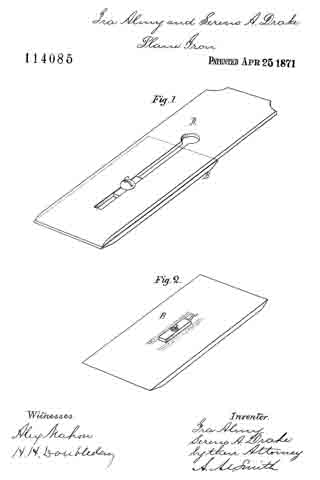
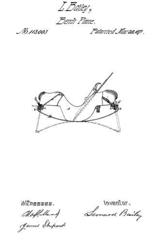
The accompanying drawing shows a side elevation, partly in section, of a plane-stock of my invention.

A designates the stock proper, which I prefer to make of cast metal; but it may be made of any suitable material. B designates the flexible face-plate, which is made of spring-steel, and secured to the under side of the stock A, near the center of its length, by screws or rivets, in the ordinary manner.

At each end of the face-plate B is secured an arm, a a’, connected thereto by means of a suitable hinge, b b’. The arms a a’ pass through the rocking shafts c c’, which shafts are pivoted in each end of the stock A, in such manner as to easily rock or partially rotate.

By means of the set-screw d (shown at the left in the drawing) the arm a may be secured firmly in the rocking shaft c; or, if desired, the arm a’ may be threaded and held in place by a nut, d’, upon each side of the rocking shaft, as shown at the right in the drawing.

The peculiar mechanism employed to secure or fasten the arms a a’ in the rock-shafts c is immaterial to my invention. Each end of the stock A is made hollow or open, to allow free play to the arms af a a’.

The broken lines in the drawing indicate the position of the arms a a’ and faceplate B, with the latter bent into a concave form.

By releasing the set-screw d, so as to allow the arm a, to pass freely through the rocking shaft c, the ends of the face-plate B may be bent upward, forming the latter into a convex form.

The movement of either arm a a’, in passing through the shaft c causes said shaft to rock on its pivots, when the end n, of such arm a a’ moves in an inward as well as upward direction, and rests (when the ends of the face-plate B are bent upward to their full capacity) in the hollow of the stock A, as shown in the drawing.

The face-plate B may be set with its ends at any point between the two positions herein shown.
I claim as my invention —

In a flexible-faced plane-stock, substantially as described, the rocking shaft c c, pivoted in the stock A, and receiving the arms a, a’ of the face-plate B, all substantially as and for the purpose described.

LEONARD BAILEY.

Witnesses:
JAMES SHEPARD,
CHAS. L. MEAD.

No. 64,341 – Improvement In Plane-Irons (S. Markee) (1867)

[paiddownloads id=”124″]64341


United States Patent Office.


S. MARKEE, OF AUBURN, NEW YORK, ASSIGNOR TO HIMSELF AND JOHN M. EASTERLEY, OF SAME PLACE.

Letters Patent No. 64,341, dated April 30, 1867.
_________________

IMPROVEMENT IN PLANE-IRONS.

_________________

The Schedule referred to in these Letters Patent and making part of the same.

_________________

TO ALL WHOM IT MAY CONCERN:

Be it known that I, S. MARKEE, of Auburn, in the county of Cayuga, and State of New York, have invented a new and useful Improvement in Plane-Irons; and I do hereby declare that the following is a full, clear, and exact description thereof, which will enable others skilled in the art to make and use the same, reference being had to the accompanying drawings, forming a part of this specification, in which —

Figure 1 is an under side view of the plane-iron, showing the sliding-nut.

Figure 2 is a longitudinal section of the same, taken through the line x x, fig. 1.

Figure 3 is a cross-section of the same, taken through the line y y, fig. 1.

Figure 4 is a detail sectional view, taken through the line z z, fig. 2, showing the under side of the sliding-nut.

Similar letters of reference indicate like parts.

My invention has for its object to furnish an inaproved double plane-iron, simple and cheap in construction, and convenient in operation; and it consists, first, in attaching the cap to the plane-iron by a screw and sliding-nut; and, second, in the sliding-nut in combination with the plane-iron cap and screw, as hereinafter more fully described.

A is the plane-iron, which has a longitudinal slot, as shown, for the passage of the screw B, which secures the cap C to the plane-iron. The upper end of this slot is enlarged so that the nut D can he passed through it.

The cap C is made of sheet steel, slightly curved in its lower part, as shown in fig. 2. Through this cap is made a hole for the passage of the screw B. The screw B passes through the cap C and through the slot in the plane-iron A, and screws into the sliding-nut D, as shown in fig. 2. This nut is made with a projecting part or flange, as shown in figs. 2, 3, and 4, which its into the slot formed in the plane-iron A, and slides along said slot in adjusting the cap C upon the plane-iron A. By this construction it is not necessary to make the cap C as heavy as it was formerly made, when it had to be made thick enough to receive and hold the screw that held the cap and plane-iron together. This construction enables me to place the head of the screw on the upper side of the plane-irons, making it much more convenient to adjust the cap in proper position with reference to the cutting edge of the plane-iron than when the head of the connecting-screw was on the under side of the plane-iron, as was the case when the cap and plane-iron were connected together in the ordinary manner.

What I claim as new, and desire to secure hy Letters Patent, is —

The plane-iron, consisting of the slotted iron A, curved cap C, flanged sliding-nut D, and screw B, arranged and operating substantially as described for the purpose specified.

The above specification of my invention signed by me this 7th day of March, 1866.

S. MARKEE.

Witnesses:
B. J. IVES,
R. P. STOW.

No. 121,406 – Improvement In Bench-Planes (Sidney W. Palmer And Elliot G. Storke) (1871)

[paiddownloads id=”189″]121406


UNITED STATES PATENT OFFICE.

_________________

SIDNEY W. PALMER AND ELLIOT G. STORKE, OF AUBURN, NEW YORK,
ASSIGNORS TO WILLIAM J. MOSES, OF SAME PLACE.

IMPROVEMENT IN BENCH-PLANES.

_________________

Specification forming part of Letters Patent No. 121,406, dated November 28, 1871.

_________________

To all whom it may concern:

Be it known that we, SIDNEY W. PALMER and ELLIOT G. STORKE, of Auburn, in the county of Cayuga and in the State of New York, have invented certain new and useful Improvements in Bench-Planes; and do hereby declare that the following is a full, clear, and exact description thereof, reference being had to the accompanying drawing making a part of this specification, in which —

Figure 1 is a plan view of our improved plane. Fig. 2 is a vertical longitudinal section of the same on the line x x of Fig. 1, and Fig. 3 is a vertical cross-section on the line z z of Fig. 2.

Letters of like name and kind refer to like parts in each of the figures.

Our invention is an improvement in that class of bench-planes having metallic stocks; and it consists, principally, in the employment upon the lower side of the pivoted cap of a central rib extending the whole length of said cap, substantially as and for the purposes hereinafter shown. It consists, further, in a cap pivoted at or near its center transversely to the stock, substantially as and for the purpose hereinafter set forth. It consists, further, in the construction of the bearings upon which the heel of the bit rests, substantially as and for the purpose hereinafter specified. It consists, further, in the relative arrangement of the bearings for the heel of the bit with those employed for the body of the same, substantially as hereinafter shown and described. It consists, finally, in the combination of the above-named bearings with the center pivoted cap, substantially as and for the purpose hereinafter set forth.

In the annexed drawing, A represents the name or stock, provided at either side with an upward-projecting flange, B, for inclosing and supporting the cap, and having near its forward end a suitable transverse opening, C, ibr the reception ef the lower or cutting end of the bit, which opening is made variable in width by means of a plate, D, that corresponds in width to the length thereof, and sliding longitudinally within a recess formed in the face of the stock, is secured in position, when adjusted, by means of a screw which projects upward through a longitudinal slot within said stock, and is provided upon its upper end with a nut, E. Secured within or upon the upper end of the nut E is a wooden knob, E’, within which is in turn secured a metallic stud or start-pin, e, the upper end of which is considerably enlarged so as to enable it to resist a blow from a hammer when it is desired to start back the bit. Projecting vertically upward from the stock A, near its longitudinal center, is a diaphragm, F, which from the upper edges of the flanges B curves inward and upward and terminates in two lugs, f separated by means of a notch, f’, upon which, when in position, the body of the bit G rests. The notch f’ is deepened sufficiently to permit of the passage of the screw g’ of the cap G’, by which means less space vertically is required for the removal of the bit than would otherwise be the case. At a short distance in rear of the opening C are placed two other lugs, H, which correspond in width and relative transverse position with those above described, and furnish a bearing for the heel of the bit. It will be readily seen that being supported at but two points midway between its transverse center and edges the bit must invariably have a firm bearing, however unequal its thickness or uneven its heel. Pivoted to and within the upper edges of the flanges B is a cap, I, having the usual curved form and provided at and through its upper and rear end with a suitable set-screw, K. Instead of the usual transverse rib for the reception of the pivot-rod L, a longitudinal rib, M, extends through the center of the cap, and not only contains said rod, but also strengthens said cap and enables other portions ofthe same to be made much lighter than would otherwise be practicable.

By making the opening through the rib M for the passage of the pivotal rod L slightly larger than said rod the cap will be enabled to adjust itself vertically to the bit, however unequal in thickness the same may be at its lower end. Another advantage possessed by the longitudinal rib is that it not only offers no obstruction to the center of the bit, but rather furnishes a guide for the same, while in caps where the transverse rib is employed great care is required in inserting the bit to avoid hitting said rib with the same and injuring its cutting-edge.

Having thus fully set forth the nature and merits of our invention, what we claim as new is —

1. In metallic bench or other planes a pivoted cap, provided upon its lower side with a central longitudinal rib, substantially as and for the purpose specified.

2. The cap I, pivoted loosely at or near its transverse center, substantially as and for the purpose shown.

3. The arrangement of the lugs or bearings H upon the stock A, substantially as shown and for the purpose described.

4. The stock A, provided with the bearings H and f arranged substantially as and for the purpose set forth.

5. In combination with the bearings H and f and a suitable bit, the cap I, pivoted at or near its transverse center, substantially as and for the purposes specified.

In testimony that we claim the foregoing we have hereunto set our hands this 10th day of August, 1871.

ELLIOT G. STORKE.
SIDNEY W. PALMER.

Witnesses:
HORACE T. COOK,
JAY E. STORKE.

No. 122,339 – Improvement In Bench-Planes (Charles E. Torrance) (1872)

[paiddownloads id=”190″]122339


UNITED STATES PATENT OFFICE.

_________________

CHARLES E. TORRANCE, OF HOLYOKE, MASSACHUSETTS.

IMPROVEMENT IN BENCH-PLANES.

_________________

Specification forming part of Letters Patent No. 122,339, dated January 2, 1872.

_________________

To all whom it may concern:

I, CHARLES E. TORRANCE, of Holyoke, Hampden county, Commonwealth of Massachusetts, have invented certain Improvements in Bench-Planes, of which the following is a specification:

Nature and Objects of the Invention.

My invention relates to the combination, with the bed piece and cutters of a metal plane, of two spurs or projections proceeding from the inner sides of the bed piece in front of the cap piece of the plane-iron, for the purpose of acting as a fulcrum; of a surface inclining from the rear side of the plane-iron within the bed piece tor the purpose of acting as a bearing for a wedge; and of a wedge extending across the plane-iron, also within the bed piece, and for the purpose of being inserted between the inclined surface behind the plane-iron and the plane-iron itself, to enable the size ofthe shaving to be regulated by the adjustment of the plane and cap-irons within the mouth of the plane; the object of my invention being to enable the construction of metal planes to be so simplified that when the bed piece is cast the addition of a wooden wedge is all that is needed to enable the cutters, when inserted, to be quickly and firmly adjusted to any bite.

In the drawing, Fig. 1 is a side sectional view; Fig. II, a vertical cross-section on the line x y; and Fig. III, a view of the wedge.

General Description.

D is the bed piece, cast in one piece with the projections A A opposite each other at points upon the inner sides of the bed piece, so that the cap-iron J bears against them near the upper end of its curve, and when the pressure needed for the most advantageous working of the plane-iron H can be obtained by the insertion or withdrawal of the wedge B. Cast also upon the bed piece are the surfaces C C, raised from the inner sides, as shown in Fig. I, and extending sufficiently far to enable the wedge to be accessible for adjustment. The sides of these upon which the wedge B slides are deflected from the inner side of the plane-iron to assist the action of the wedge. The stock in the base of the bed piece is made thicker on the inner face of the mouth to form the bearing b, which rises in contact with the inner surface of the plane-iron to hold the same when the cap-iron is compressed by the insertion of the wedge, and the point of contact between the bearing b and plane-iron H being below the projections A A the insertion of the wedge acts to compress the toes of the two irons H and J, and vary their points of contact, while both are securely braced against all possibility of buckling or rising from their bed. The wedge B, which I prefer to make of wood, as being lighter than metal and less apt to slip or slide upon a metal surface, is formed as shown in Fig. III, so as to, for convenience, constitute two wedges connected by a handle easily grasped.

There is nothing new in my plane in either the cutters, handle, or the knob; but by my improvements the cost of manufacture is reduced more than one-half, and a simple and effective tool is made that cannot get out of order, and having for its only detachable parts the wedge and the irons.

New having described my invention, what I claim as new, and desire to secure by Letters Patent, is —

Claim.

In combination with the irons J and H, and cast-iron bed-plate D with its bearing surfaces c c and b, the projections A A cast upon the bed-plate and wedge B, the parts being constructed and arranged as shown and described.

CHARLES E. TORRANCE.

Witnesses:
R. F. HYDE,
E. N. SMITH.

No. 114,590 – Improvement In Stops For Carpenters’ Plows (Thomas Nichols) (1871)

[paiddownloads id=”185″]114590


United States Patent Office.


THOMAS NICHOLS, OF VICKSBURG. MISSISSIPPI.

Letters Patent No. 114,590, dated May 9, 1871.
_________________

IMPROVEMENT IN STOPS FOR CARPENTERS’ PLOWS.

_________________

The Schedule referred to in these Letters Patent and making part of the same.

_________________

I, THOMAS NICHOLS, of Vicksburg, in the county of Warren and State of Mississippi, have invented certain Improvements in Stops for Wood-Plows, of which the following is a specification.

Nature and Objects of the Invention.

My invention relates to the combination of a thumb-nut and screw with a stop in such a manner that the said stop may be retained in any desired position, the object of this part of my invention being to set the stop so as to plane a groove of any desired depth.

Description of the Accompanying Drawing.

Figure 1 is a front elevation of a machine embodying my invention.
Figure 2 is a side elevation of the same.

General Description.

A is a block intended to represent the wood part of a plow.
B is the stop, which should be made of brass or other metal, and is held in position by the screw D, from which latter, by means of the flat part on top, the stop is elevated or depressed; and when adjusted so as to regulate the depth of groove to he planed it can be securely fastened in that position by tightening up the thumb-nut E, which is made to turn independent of the screw D.

F is a collar secured to the screw D by means of peg G, which keeps it firmly in its place.

Claim.

I claim as my invention —

The combination, with the thumb-nut E and screw D, of the collar F and stop B, substantially as and for the purpose hereinbefore set forth.

THOMAS NIGHOLS. [L. S.]

Witnesses:
Z. P. DEDERICK,
H. N. MARTIN.

No. 114,085 – Improvement In Plane-Irons (Ira Almy And Sereno A. Drake) (1871)

[paiddownloads id=”184″]114085


United States Patent Office.


IRA ALMY AND SERENO A. DRAKE, OF COVERT, NEW YORK.

Letters Patent No. 114,085, dated April 25, 1871.
_________________

IMPROVEMENT IN PLANE-lRONS.

_________________

The Schedule referred to in these Letters Patent and making part of the same.

_________________

To all whom it may concern:

Be it known that we, IRA ALMY and SERENO A. DRAKE, both of Covert, Seneca county, State of New York, have invented certain new and useful Improvements in Plane-Iron, of which the following is a full, clear, and exact description, reference being had to the accompanying drawing making part of this specification, in which —

Figure 1 is a view of our improved plane-iron with the parts arranged in a proper working relation to each other, and Figure 2 is a detached view of the lower iron or bit with the cap removed.

Similar letters of reference denote corresponding parts in both figures.

The invention relates to the construction of double irons — that is, those composed of two parts — to wit: a lower or cutting~blade or bit, and an upper part or cap, this cap being attached to the bit by means of a screw.

These double irons are usually employed in jointing-planes and srnoothing-planes, when smooth and accurate work is required.

The invention consists in making the bit reversible, having both ends constructed with a cutting-edge, in combination with a cap having a longitudinal slot therein, as will be hereinafter fully explained.

In the drawing —

A represents the cap, made, preferably, of wrought or malleable iron, and substantially in the form of an ordinary single plane-iron, except that, when in proper position in the plane-stock, the bevel at the lower end is upon the upper side instead of on the lower side, as it is in a plane-iron.

This cap is provided with a long narrow slot, enlarged into a circular form at the upper end, to admit the passage of a screw, which will soon be described.

B is the bit or cutting-blade, made in the form shown plainly in fig. 2. Both ends of this bit are made in the same shape, so that they can be used for cutting-edges, and, in practice, we deem it advisable to make it entirely of steel.

C is a set-screw, the shank of which is adapted to engage with a thread cut in the central portion of the bit, as at b, fig. 2.

By preference we provide the bit with a rectangular rib, B’, of such a width as will allow it to slip into the slot c, and of a height a little less than the thickness of cap A.

The object of this rib B’ is to assist in maintaining the bit and cap in a proper relation to each other when they are connected by means of the screw, as in fig. 1, and more particularly for the purpose of adjusting the parallelism of the cutting-edge and the bottom or working face of the plane-stock; but, as this rib may not in all eases be found to he essential, we do not wish to be limited to its use.

The construction and operation of the device is so simple that a more detailed description is not deemed necessary.

Having now described the invention, What we claim as new, and desire to secure by Letters Patent, is —

The herein-described plane-iron, consisting of the cap A and the reversible bit B, substantially as shown and described.

IRA ALMY.
SERENO A. DRAKE.

Witnesses:
JAMES C. KNIGHT,
O. G. WHEELER.

No. 119,133 – Improvement In Carpenters’ Planes (Henry N. Frederick) (1871)

[paiddownloads id=”187″]119133


UNITED STATES PATENT OFFICE.

_________________

HENRY N. FREDERICK, OF HANCOCK, NEW YORK.

IMPROVEMENT IN CARPENTERS’ PLANES.

_________________

Specification forming part of Letters Patent No. 119,133, dated September 19, 1871.

_________________

To all whom it may concern:

Be it known that I, HENRY N. FREDERICK, of Hancock, in the county of Delaware and State of New York, have invented a new and Improved Carpenters’ Plane; and I do hereby declare that the following is a full, clear, and exact description thereof, which will enable others skilled in the art to make and use the same, reference being had to the accompanying drawing forming part of this specification.

Figure 1 represents a side view, partly in section, of my improved carpenters’ plane. Fig. 2 is a vertical transverse section of the same taken on the plane of the line c c, Fig. 1.

Similar letters of reference indicate corresponding parts.

My invention consists in the improvement of carpenters’ planes, as hereinafter described and subsequently pointed out in the claim.

A, in the drawing, represents the block or frame of a carpenter’s plane. B is the planing-iron. The face of the iron has a toothed portion, a, into which mesh the teeth of a segment, C. This segment is formed at the lower end of a lever, D, that turns on a pin, b, whose bearings are in the sides of the plane. By swinging the lever D on its pivot, the iron B will be set up or down, as may be desired. E is a slotted lever pivoted to the plane A. By means of a thumb-screw, d, fitting through the lever E into D, the latter can be clamped to lock the iron B in any suitable position. Other means for thus securing the lever D and iron, may, however, be substituted for lever E and screw d.

Having thus described my invention, I claim as new, and desire to secure by Letters Patent —

The toothed segment C pivoted to the plane A, and combined with the iron B, which has the toothed portion a, substantially as herein shown and described.

HENRY N. FREDERICK.

Witnesses:
M. D. WHEELER,
MILO SCUTT.

No. 114,613 – Improvement In Planes (James K. P. Smith) (1871)

[paiddownloads id=”186″]114613


UNITED STATES PATENT OFFICE.

_________________

JAMES K. P. SMITH, OF JEFFERSONVILLE, INDIANA, ASSIGNOR T0 HIMSELF
AND L. S. SHULER, OF SAME PLACE.

IMPROVEMENT IN PLANES.

_________________

Specification forming part of Letters Patent No. 114,613, dated May 9, 1871.

_________________

To all whom it may concern:

Be it known that I, JAMES K. P. SMITH, of Jeffersonville, in the county of Clark and State of Indiana, have invented a new and useful Improvement in Joiners’ Planes; and I do hereby declare that the following is a full, clear, and exact description thereof, which will enable others skilled in the art to make and use the same, reference being had to the accompanying drawing, forming part of this specification.

This invention relates to improvements in joiners’ planes; and it consists in an improved arrangement of screw clamping and setting apparatus and a metal casting fitted in a socket in the wood stock behind the throat for clamping the plane-bit against, after setting, to hold it firmly, and for the support of the adjusting-screw, all as hereinafter described.

Figure 1 is a longitudinal sectional elevation of my improved plane. Fig. 2 is a longitudinal section through the casting. Fig. 3 is a perspective view of a part of the clamping apparatus.

Similar letters of reference indicate corresponding parts.

A represents two vertical plates, joined by the cross-bar B and the top plate, C. Said plates have the front ends inclined in the same angle the plane-bit D is to be set in, and these ends have rabbets E for the plane-bit to rest in at each edge. This casting is a little wider than the plane-bit, and not quite as deep as the height of the wood stock F. It is let into a deep recess, G, behind the throat H, so that the top plate, which is wider than the recess, will rest at the projecting edges on the top of the stock F to be screwed down to it.

The end of plate C toward the plane-bit has a boss, I, perpendicular to the line of the plane-bit, for the support of the adjusting-screw K, for setting the bit, which screw is fitted in a hole through said boss, and provided with a collar, L, which, together with the head of said screw, prevents end movement. This screw works in a stud, M, projecting from the back of the plane-bit, for adjusting the latter.

N represents clamping-bars, pivoted to the prongs O of a yoke, P, at the insides of said arms near the ends, to be clamped against the front side of the plane-bit for pressing the latter against the ends of plates by the clamping-screw Q, screwing through the end R of said yoke, and extending rearward through the end of the planestock, where it is provided with a thumb-bit, S, for turning the screw. The said arms O work in slots T in the ends ot’ the plates A, and extend beyond the edges ofthe plane-bit for holding the bars N against the front side. The said bars are pivoted to the arms for allowing them to bear fair upon the plane-bit.

The inner end of the screw has a bearing in the cross-bar B, which has a socket, T, made for it. The said screw, being turned by the thumb-bit S to draw the yoke toward the rear, will clamp the plane-bit firmly against the ends of the plates, as clearly shown, and being turned the other way releases it.

To remove the plane-bit the clamp is released as much as it can readily be, and the bit forced down by screw K till stud M is disengaged; then the upper end of the bit is tilted forward to clear the stud M from the lower end of screw K, when the bit may be lifted out.

Having thus described my invention, I claim as new and desire to secure by Letters Patent —

1. The combination, with the plane-bit and the wood stock, of the casting A B C, yoke P, clamps N, and clamping-screw Q, all substantially as specified.

2. The combination, with the above, of the adjusting-screw K, substantially as specified.

JAMES K. P. SMITH.

Witiiesses:
HENRY B. DIBBLE,
JNO. W. SULLIVAN.

No. 124,435 – Improvement In Spoke-Shaves (Jacob Groben) (1872)

[paiddownloads id=”192″]124435


UNITED STATES PATENT OFFICE.

_________________

JACOB GROBEN, OF BUFFALO, NEW YORK, ASSIGNOR TO HIMSELF AND
SAMUEL D. SIKES, OF SAME PLACE.

EMPROVEMENT IN SPOKE-SHAVES.

_________________

Specification forming part of Letters Patent No. 124,435, dated March 12, 1872.

_________________

Specification describing certain Improvements in “Spoke-Shaves,” invented by JACOB GROBEN, of Buffalo, in the county of Erie and State of New York.

Nature of the Invention.

This invention relates to certain improvements in spoke-shaves, and it consists of the combination of certain parts as will hereinafter be set forth.

General Description.

In the drawing, Figure 1 is a back elevation. Fig. 2 is a bottom-plan view. Fig. 3 is a cross-section.

A represents the stock, B the cutter or knife, and C the face-guide. The knife is of a rectangular form, without lugs or ears to hold it; but has, instead, slanting edges, which are chamfered off, and which fit in metal sockets a a’, having slanting-grooves b b’, into which these edges set. These goooves are set slanting toward the front, to prevent the knife from slipping out, but more particularly to allow the knife to be set forward whenever the edge becomes worn or ground down, so that the space between the knife and guide may be kept always at the right adjustment. In order to hold the knife in position after it is set forward, I provide one or both of the sockets a a’ with a slot, c, through which a set-screw passes, by which the sockets can be set a little forward, as may become necessary, to keep the knife in proper place. On the under side of the sockets I form lugs e e, which fasten into the wooden stock by the pressure of the screw. The face-guide C, which graduates the cutting, works up and down in the grooves d d’, formed in the side of the stock A. It is held at any height by means of a single screw, E. By these simple devices the throat can be set at any size, and down to the very smallest space, so that cross-grained stuff can be worked just as well as straight stuff, and prevents the knife “eating ” into the wood.

This device of mine makes a very simple but very durable spoke-shave, only being required that the knife should be renewed occasionally to last a long time. It will adjust to a curved as well as a straight-cutter, and will be excellent for sweep-work.

Claim.

The slotted plates a a’, formed with the lugs e, and inclined grooves b b’, in combination with the knife B, and with the movable face guide-plate C, and its adjusting-screw E, all constructed and operating as set forth.

ln witness whereof I have hereunto signed my name in the presence of two subscribing witnesses.

JACOB GROBEN.

Witnesses:
J. R. DRAKE,
C. N. WOODWARD.

No. 122,609 – Improvement In Carpenters’ Planes (Henry A. Holt) (1872)

[paiddownloads id=”191″]122609


UNITED STATES PATENT OFFICE.

_________________

HENRY A. HOLT, OF WILTON, NEW HAMPSHIRE.

IMPROVEMENT IN CARPENTERS’ PLANES.

_________________

Specification forming part of Letters Patent No. 122,609, dated January 9, 1872.

_________________

To all whom it may concern:

Be it known that I, HENRY A. HOLT, of Wilton, in the county of Hillsborough and State of New Hampshire, have invented certain new and useful Improvements in Carpenters’ Planes, of which the following is a full, clear, and exact description, reference being had to the accompanying drawing making part of this specification, in which —

Figure 1 represents a central longitudinal section of an ordinary bench~plane containing my improvement. Figs.2 and 3 represent the improvement detached from the plane. Fig. 4 represents, also, a section of a plane and certain modifications of my invention.

This invention relates to certain improvements in the bench-planes used by carpenters and other wood workers, whereby the face of the plane is slightly elevated above the material being planed, to prevent dragging the iron and dulling its cutting-edge when drawing the plane backward.

This invention consists of a spring, actuated and yielding disk or plate g, applied to the face of the plane and projecting a little beyond its surface and actuated by a spring, f to press the disk outward and hold the face of the plane a little above the surface of the material being reduced. The apparatus may be applied either back of the iron or forward ofthe iron, as shown in the drawing.

In the said drawing, A represents the plane-stock or wood provided with the usual plane-bit B and a wedge, C, or other device for holding the bit or plane-iron. At any convenient distance, either forward or back of the cutting-edge of the bit, a metal flange, b, is inserted in the face of the plane, either on a line with its face surface or a little beyond it, as shown, and this flange b is fastened to the plane-stock generally by screws. The flange b has a central opening, and above this is a bail or brace, d, rising from the flange. The disk or plate g is applied within the flange b, fitting loosely in the aperture. A stem or spindle, n, rises above the plate, and its upper end is furnished with a nut, e, or other equivalent means for adjusting the plate, between which and the under side ofthe bail or stirrup d I apply a spring, f, which may be adjusted or regulated to produce the desired downward pressure upon the disk, and keep it beyond the face of the plane, the face of the disk being somewhat rounded to prevent its edge catching in the wood. Instead of applying the adjusting nut e at the top of the stem this nut may be applied near the roots of the stem above the plate g’, and the spring f applied between the top of the nut and the under side of the stirrup; but in this case the stirrup should be contracted or the sides brought nearer together above the plate, so as to hold the nut when turning the disk to adjust its surface to and beyond the face of the plane. In Figs. 1 and 3 I have shown a disk having a rim-ratchet, S, and arms it for adjusting the plate.

The above-named parts may be employed or dispensed with. They are useful at times, but as at present advised they are not a necessity.

Instead of the parts previously described the flange b may be constructed in a more elongated form, and the disk or plate pressed downward by a flat spring, f1, engaging with the stem of the disk, or by a coiled stirrup-spring, ff2, as shown in Fig. 4, the disk being provided on its upper side with projecting lugs a or a flange to prevent its being pressed too far beyond the surface of the plane.

It will be observed that the flange b is adjustable to the face of the plane or beyond it by rubber washers, k, applied between the flange and the plane wood, and generally around the holding-screws, which confine the flange to the plane-stock, and these elastic washers provide for the easy and quick adjustment of the flange whenever desired, while the disk or plate g is as easily adjusted by turning it any part or the whole of a revolution with a screw-driver inserted in a nick, c’, in the face thereof.

I claim as my invention —

1. The combination of the yielding disk or plate g and its actuating spring L arranged upon a flange, b, or other support, the spring operating to press the disk outward and hold the face ofthe plane above the surface of the material, in the manner and for the purpose specified.

2. The elastic washers it and adjusting-screws in combination with and making the flange b adjustable to the face of the plane, in the manner and for the purpose set forth.

HENRY A. HOLT.

Witnesses:
WM. EMERSON,
C. P. EMERSON.

No. 126,519 – Improvement In Carpenters’ Planes (Orril R. Chaplin) (1872)

[paiddownloads id=”193″]126519


UNITED STATES PATENT OFFICE.

_________________

ORRIL R. CHAPLIN, OF BOSTON, ASSIGNOR TO HIMSELF AND CHARLES H.
BALLARD, OF WORCESTER, MASSACHUSETTS.

IMPROVEMENT IN CARPENTERS’ PLANES.

_________________

Specification forming part of Letters Patent No. 126,519, dated May 7, 1872.

_________________

To all whom it may concern:

I, ORRIL R. CHAPLIN, of Boston, in the county of Suffolk and State of Massachusetts, have invented certain new and useful Improvements in Joiners’ and Carpenters’ Planes, of which the following, taken in connection with the accompanying drawing, is a specification:

Nature anal Objects of the Invention.

My invention relates, in the first place, to the means employed to secure the cutter to the stock and to adjust the same when so secured, and is more particularly applicable to planes the stocks of which are made wholly or in part of metal; and it consists in the employment of a saddle or rest-plate which forms the bearing for the upper portion of the cutter, and to which it is secured by the clamping device, said saddle being secured to the plane-stock by a single screw passing through a slot in the saddle and so adjusted that the saddle may be moved endwise to adjust the “tooth” of the cutter, as will be described. It also consists in the use of a screw cam-lever, the thread of which works in a half-nut formed upon or secured to the under side of the saddle or cutter for the purpose of adjusting the cutter to give the desired “tooth” to the same. It also consists in the use of a clamping-plate provided with a lug on either side thereof projecting downward, each terminating with a hook at its lower end, which engages with the under side of the saddle and acts as a fulcrum for the clamping-plate when the screw in its upper end is operated to bind the cutter, saddle, and clamping-plate together.

My invention relates, in the second place, to the construction of the cutter and cap; and it consists in the use, as a substitute tor the ordinary cap now in general use on all plane-irons or cutters for dressing hard wood or cross-grained stock, of a short plate of metal secured loosely by its middle to the lower end of the clamping-plate by two or more rivets, said plate being so formed that it can only bear upon the cutter at its upper and lower edges, and the clamping-plate being so formed that it can bear upon said plate at or near its middle only in a line across its width, said plate being so secured to the clamp that it is susceptible of a slight rocking motion, so that it may accommodate itself to the surface of the cutter. By the use of this combined clamp-plate and cap, the lower edge of which is of the proper form and adjusted to the proper point to serve all the purposes of the common cap of a double plane-iron or cutter, I am enabled to use a plain cutter-iron without slots or holes of any kind, thus reducing the cost of the cutter, and also the weight of the plane.

My invention relates, in the third place, to the means employed to reduce the adhesion of the plane-stock to the material being dressed; and it consists in perforating the race of the plane-stock with a series of holes, thereby reducing the area of the stock exposed to atmospheric pressure.

Description of the Drawing.

Figure 1 is a plan of my improved plane. Fig. 2 is a side elevation; Fig. 2, a longitudinal section on line x x on Fig. 1. Fig. 4 is a section on line z z on Fig. 2, looking toward the throat otf the plane. Figs. 5 and 6 are details of the saddle, and Fig. 7 is a plan of the cutter.

General Description

A is the plane-stock made of metal; B, the handle; and C, a knob on the forward end upon which to rest the left hand while operating it. The handle B and knob C are secured to the metallic stock by means of the screw-bolts a and b, respectively. Upon the upper side of the stock, just in the rear of the throat c, is cast a boss, D, sloping backward toward the handle at about the same angle that it is desirable to give to the cutter, to the upper side of which is secured the saddle E by the screw d passing through the slot e without bringing the head to bear upon the saddle so as to bind it to the stock. The saddle E is provided with a shoulder, e’, on either side, against which the lugs on the clamp, to be described, strike to determine the position of the clamp in an obvious manner. F is the cutter made of the form shown in Fig. 7, the upper or rear portion being made narrower than the cutting end to facilitate the application and removal of the clamp, and also to allow play for adjusting the cutting-edge square with the face of the stock at the throat if the cutter should not be ground perfectly square. G is the clamp, provided at about the middle of its length with two lugs, f f, (one on either side,) projecting downward and terminating in hooks f’ f” upon their inner faces, as shown in Fig. 4. The clamp G is also provided at its upper-end with a thumb-screw, H, by which it is secured in place, as will be presently explained. To the under side of the lower end of the clamp is riveted loosely the plate g, the lower end of the clamp being so formed as to rest upon the plate near its middle without touching at any other point, and the plate g being so fitted that it is susceptible of a slight rocking motion. This plate serves the purpose of the ordinary cap upon a double plane-iron or cutter, the clamp and this plate combined serving the double purpose of clamp and cap with less cost to manufacture, less trouble to adjust and less weight to handle than by the use of the old style double-iron. To the upper or rear end of the boss D is pivoted the lever I by means of the pin h. The hub of the lever I is partially surrounded by the segments of screw-threads s s, which work in the half-nut i upon the under side of the saddle E, and by a movement of the lever I to the right the cutter is forced outward, and if the lever be moved to the left the cutter will be drawn in in an obvious manner. The face of the plane-stock is perforated with a series of holes, as seen at n n n in Fig. 3, for the purpose of reducing the area exposed to the pressure of the atmosphere.

It has been a serious objection to metallic plane-stocks as heretofore constructed that, owing to the more nearly perfect surfaces of their faces, the pressure of the atmosphere upon their upper surfaces, when working upon stock planed to nearly the same level surface, causes an adhesion of the plane to the wood, which materially increases the labor of operating it, especially when using a jointer or large plane. This difliculty is not so serious with wooden plane-stocks, for the simple reason that they are seldom so true but that more or less air is between the plane-stock and the material being worked. By perforating the face of the plane the pressure is reduced just in proportion to the area removed by the perforations without injuring the face of the plane for any practical purpose.

The operation of my improvement is as follows: The saddle E is secured to the stock, as shown, by means of the screw d, the under side of the head being at such a point that when the saddle is brought to bear against it the top of the saddle shall be slightly below the inclined surface in the stock of the plane just in the rear of the throat, so as to insure a good bearing of the cutter at its extreme lower end to prevent. it from chattering. The lever I is then moved to the left, the cutter placed in position on the saddle, and the combined clamp and cap is slipped down over the cutter and saddle till the lugs f f come in contact with the shoulders e’ e’ upon the saddle. The plane is then taken in the left hand, with the thumb pressing upon the clamp to hold it in position, and the edge of the cutter is adjusted to the cap, when the thumb-screw H is operated, which forces the cutter down upon the upper end of the saddle, and, forcing the half-nut upon its under side down upon the screw-cam on the hub of the lever I and acting upon that as a fulcrum, lifts the lower end of the saddle hard against the head of the screw d, thus holding the saddle rigidly in its place, and as the lower end of the saddle is still slightly below the incline upon which the lower end of the cutter rests, the clamp, acting upon the hooks f’ f’ as a fulcrum, forces the lower end of the cutter firmly onto its seat.

To adjust the “tooth” of the cutter to take a thick chip, move the lever I to the right hand, and to take a thin chip move it to the left hand.

Having thus described my invention, I do not claim anything contained in the patent No. 64,790, granted to Nelson Palmer, May 14, 1867, for “Bench-Plane;” but

What I claim as new, and desire to secure hy Letters Patent of the United States, is as follows:

1. In combination with the saddle E, provided with the slot e and the half-nut i, and secured to the plane-stock by the screw d, I claim the cam-lever I, constructed and operating substantially as described.

2. The clamp G, provided with the lugs f fand hooks f’ f’, in combination with the saddle E, having the shoulders e’ e’ thereon, for determining the position of the clamp, substantially as described.

3. I do not claim broadly a cap-plate attached to the clamp instead of the bit or cutter, for I am aware that that has been done before; but I claim the cap-plate g, made of the form shown and secured by its middle to the clamp G, by being loosely riveted thereto in such a manner that it may be free to accommodate itself to the surface of the cutter upon which it bears at its upper and lower edges, substantially as described.

4. The combination and arrangement of the screw cam-lever I, the saddle E, the cutter F, the clamp G, and the cap-plate g, all constructed, applied, and operated substantially as herein described.

Executed at Boston this 14th day of February, 1871.

ORRIL R. CHAPLIN.

Witnesses:
CHARLES H. BALLARD,
N. C. LOMBARD.

No. 120,212 – Improvement In Carpenters’ Planes (Russell Phillips) (1871)

[paiddownloads id=”188″]120212


UNITED STATES PATENT OFFICE.

_________________

RUSSELL PHILLIPS, OF BOSTON, MASSACHUSETTS.

IMPROVEMENT IN CARPENTERS’ PLANES.

_________________

Specification forming part of Letters Patent No. 120,212, dated October 24, 1871.

_________________

To all whom it may concern:

Be it known that I, RUSSELL PHILLIPS, of Boston, in the county of Suffolk and Commonwealth of Massachusetts, have made an invention of certain Improvements in Carpenters’ Planes; and do hereby declare the following to be a full, clear, and exact description thereof, due reference being had to the accompanying drawing making part of this specification, and in which —

Figure 1 is a plan; Fig. 2, a front elevation; Figs. 3 and 4, opposite side views; and Figs. 5 and 6, vertical sections of a combination plane embodying my improvements. Fig. 7 is a transverse section of the adjustable scoring-spurs, to be hereinafter explained; and Fig. 8, a vertical section of the key of the outermost plow-plane and the device for adjusting the same; Fig. 9, a longitudinal section of the device tor clamping the cutter of the rabbeting-plane, which will be duly explained in the context.

This invention may be considered an improvement upon that for which Letters Patent of the United States have already been issued to me. I have in this instance, as in the former, called the instrument a combination plane, since it embodies three planes of different natures, either of which may be used alone to perform its ordinary functions, if desired, while in the general combination provision is made whereby the three or two of the three planes maybe adapted to execute work unattainable by one, while still further either plane may be removed from connection with its neighbor and used as an independent tool to perform its own individual duty.

The primary elements of this combination consist, first, of a central cross-grooving and plow-plane, such central portion carrying the handle of the combination implement and supporting upon either side, in an adjustable manner, the two other primary elements of the combination, which are a rabbeting-plane and a second cross-grooving and plow-plane, the implement as a whole being susceptible of cutting the tongue and groove in matching stuff, of cutting narrow or extremely wide cross-channels or longitudinal grooves, of performing all the functions of a rabbeting-plane, and finally, of reducing wood to a certain form. in executing moldings by hand, by which much of the labor of roughing out the molding is avoided.

In the drawing accompanying and illustrating this description of my invention, A denotes a metallic rabbeting-plane, substantially of ordinary production with the exception of the absence of a handle and the employinent of a. thumb-guard or hand-rest, B, erected upon its side, the said rabbeting-plane being further distinguished from others of its class by the addition to its under side of an adjustable gauge, D, which converts it into a style of plane known as a “filister”-plane, or those in which the width of the rabbet cut by the tool is governed at pleasure, this gauge being pendent from and controlled by a horizontal arm, a, extending laterally below the plane-bed or plate, which arm in turn is mounted and slides freely upon a rod or bar, b, affixed to and departing laterally from the outer edge of the said plane-bed, and is provided with a set-screw, whereby the two may be clamped together when the desired position of the gauge is insured. Each end ofthe gauge D overlaps the upper edge of that of the plane-bed in order to insure a steady position and relieve the arm a and rod b of the thrusts and strain to which they would be otherwise subjected. A movement of the gauge D to and fro of the plane A with respect to the inner side or the latter determines the width of the cut effected by the iron E of such plane. The plane A is suspended at its outer forward part from a furcated or slotted hanger, F, which is mounted upon and depends from two horizontal parallel rods, G G’, the hanger sliding freely upon such rods, and a set-screw being combined both with the hanger and rods and the plane A, by which both the height and lateral position of such plane with respect to the central plow-plane are varied and determined. This last-named plow-plane, shown at L in the drawing, is the central member of the combination, and bears at rear end the handle H of the combination instrument, such plow-plane being virtually of ordinary construction and composed of an upright blade or sword, c, and a narrow shelf, d, at top, the iron or cutter of this plane being shown at e, while the two horizontal rods or supports G G’ before named depart laterally from this shelf at or near the forward end of the plane, as represented. The second and outermost cross-grooving plane is shown at I in the drawing as simply an upright thin blade or fence, J, carrying in the ordinary manner a cutter, K, this plane I being mounted upon and sliding to and fro of two horizontal lateral guides or rods, f f which extend from the outer side of the central plane I, the said plane being provided with a set-screw, whereby its position upon its guide-bar and its relation to the central plane L are determined. The said plane I serves as a valuable adjunct to the central plane L, inasmuch as the two together are susceptible of cutting a very wide cross-groove, while also, and detached from the other, such plane I is an entirety in itself and is an ordinary cross-groove plane. The scoring-spurs of the central plane L are shown at g g, as disposed at the forward end of such plane and affixed each to a vertical flat plate, h, the two plates overlapping each other and being situated within an orifice, i, created in the sword c and below the shelf d and at right angles to the longest plane of such sword, and remaining upon opposite sides of said sword, and consequently of the cutting-iron carried by it. Each plate h is prolonged into a vertical post, j, while disposed between these posts, and screwing through each, is a right-and-left-threaded screw, by turning which in one or the other direction the spurs are caused to approach to or recede from one another, and thus adapt them to a cutter of any width. In order to adapt the two spurs bodily together to the position of the cutter — that is, to bring the whole into alignment with the general plane of the sword c –I employ a set-screw, l, which enters the orifice i before named and serves to clamp the two spurs firmly into place together at any desired point transversely of the sword and with respect to the cutting-iron e. The cutter-iron E of the rabbeting-plane A is clamped in position upon its bed in by a cap-plate, M, to the under side of which one end of a lever, n, is pivoted, the fulcrum of this lever being a short post, o, erected upon the base of the plane and immediately in rear of the iron E, while screwing downward through the outer and longer arm p of this lever, and abutting again st the said base, is a screw, q, as shown in the drawing. Turning the screw in one direction elevates the longer arm p of the lever and forces the cap-plate M upon the plane-iron E with a powerful pressure, and confines the latter securely in place upon its bed. Reversing the motion of the screw relaxes the pressure upon the parts and permits the adjustment or removal of the cutter. The key of the central plow-plane, which confines its cutter in place, is shown at c in the drawing as a tapering or wedge-shaped block disposed between the cutter and the abutment S, making part of the shelf d hereinbefore mentioned, and the vertical movements of this key in tightening or loosening the cutter are effected by a right-and-left screw, t, which screws at one end into the abutment s and at the other through an arm, u, which constitutes the upper termination of the said key. A turn of the screw in one direction elevates and in the opposite direction lowers the key r, and the action of such key upon the cutter will be at once understood. The depth-gauge of the central plane L is shown at u as a flat horizontal plate, v, :making part of an upright bar, w, which in turn is suspended in an adjustable manner irom a carriage, x, this carriage being supported and sliding within horizontal ways or guides y y formed in the upper forward part of the sword of the plane or the shelf d, making part thereof. The carriage x and the bar u’ of the depth-gauge have each an outstanding lateral shelf, z or z’, the two being disposed opposite each other, while passing through these two shelves is a right-and-left-threaded screw, a’, by means of which the depth of the gauge with respect to the sword and cutter of the plane may be adjusted. It will be observed that the depth-gauge u may be, if desired, fixed immovably to either side thereof.

In the above combination of parts, by lowering the rabbeting-plane A it may be made to serve as a guide or stop to the central or outer plow-planes, or both combined, when used in matching stuff or other purposes, while, as before observed, such plane disposed below the base of the central plane and operating with its adjustable gauge D enables two rabbets to be cut at one and the same time, which will be found of great service in cutting uncommon or irregular moldings by hand, and in exceptional cases in tonguing and grooving. The simple and efficient mode of applying the gauge D to the rabbeting-plane enables its adjustment to be effected instantly, and secures it very firmly to the base of the plane, while it may be made to perform the office of a gauge or guide to either the rabbeting-plane carrying it or to the central plow-plane. The adjustable method of combining the rabbeting-plane and the outer prong-plane with the central plow-plane, as herein shown, enables the combination implement to be set immediately to the proper gauge for cutting the tongue and groove in matching stuff.

I claim —

1. The combination, with the central plane L, of the rabbeting-plane A attached to said central plane in the manner and by means herein shown and described, in order to adjust it both vertically and horizontally in relation thereto.

2. The combination of the three planes A, I, and L in the manner shown and described, so that either or both of the latter two planes may be removed from the former for the purposes stated.

3. The combination, with the plane A, of the adjustable gauge D and the rod or support b under the arrangement shown and set forth.

4. The combination, with the plane L, of the spurs applied thereto in the manner shown and described, to allow them to be adjusted separately or jointly with respect to the cutter of the plane.

5. The combination, with the plane A and its cutter-iron, of the lever n, pivoted to the cap-plate m, inlcrumed to the post o, and provided with the elevating device q, substantially as herein shown and set forth.

6. The combination, with the clamping-key, of the plow-plane I and its abutment of the right-and-left-threaded screw t, in the manner and for the purposes shown and set forth.

RUSSELL PHILLIPS.

Witnesses:
FREDERICK CURTIS,
WILLIAM KEEFE.

No. 112,949 – Improvement In Molding-Planes (Ellis H. Morris) (1871)

[paiddownloads id=”182″]112949


United States Patent Office.


ELLIS H. MORRIS, OF CANTON, OHIO.

Letters Patent No. 112,949, dated March 21, 1871.
_________________

IMPROVEMENT IN MOLDING-PLANES.

_________________

The Schedule referred to in these Letters Patent and making part of the same.

_________________

To all whom it may concern:

Be it known that I, ELLIS H. MORRIS, of Canton, in the county of Stark and State of Ohio, have invented a new and valuable Improvement in Molding-Planes; and I do hereby declare that the following is a full, clear, and exact description ofthe construction and operation of the same, reference being had to the annexed drawing making a part of this specifcation and to the letters and figures of reference marked thereon.

Figure 1 of the drawing is a top view of my plane;
Figure 2 is a side elevation, with the side plate removed;
Figure 3 is a vertical transverse section;
Figure 4 is a bottom view; and Figures 5, 6, and 7 are details.

My invention has relation to an improvement in planes; and It consists in providing a plane-stock with an adjustable face, capable of being molded or shaped to suit a plow-bit of any form; also, in attaching to the plane-stock an adjustable extension-gauge, designed to enable the bit to be run at any desired distance from the edge of a board or panel, as hereinafter described.

The letter A of the drawing designates my plane-stock, which may be similar in its external form to the ordinary plane-stocks in common use. The under side of the stock is channeled or excavated from side to side to receive the thin vertical sections which constitute the adjustable face of the stock.

B B represent elongated recesses or ways extending up into the body of the plane-stock, from the channel at the base, at an angle of forty-live degrees, or corresponding to the angle of the bit. These recesses serve to receive the offsets from the face-sections, presently to he described. Usually I make one of these recesses in front of the throat of the plane, and two in rear thereof.

C designates the adjustable face of my plane-stock. This is composed of two sets of thin vertical strips d, running in the direction of the length of the plane-stock. One set of these strips is situated in front ot the bit and the other is placed in rear, following the bit.

Each strip of the first set is provided with an offset or guiding-arm, e, which extends upward and backward at an angle of forty-five degrees, or parallel to the bit, into the recess B.

Each stern e is provided with a projection, h, at its upper forward corner, which is designed to engage with a stop, k, in the wall of the recess. The arm e is arranged to slide up and down in its recess, the distance to which it can descend being regulated by the position of the stop it and the projection h.

Each strip of the second or rear set is provided with two guiding-arms f f’, extending upward and rearward, parallel to the arm of the strip in front of the bit, which immediately precedes it.

The forward arm f’ of the rear strip is without a stop, and slides in a recess formed in the rear wall or the throat of the stock.

The rear arm f is similar to tue arm e ofthe forward strip, being provided with a projection, and arranged to engage with a stop in the wall of its recess which limits the descent of the strip. These stops k are placed in the recesses in such a position that they will allow the strips to descend as far as the lowest point of any one of the ordinary plow-bits in use.

These strips or sections d are usually made thin, in order that they may conform as closely as possible to the configuration of the edge of the bit. The face-edge of each strip is transversely rounded, or beveled on each side.

D D represent set-screws, passing through the wall of the plane-stock, and serving to secure the strips in their relative position to each other and to the bit after they have been properly adjusted and molded in form.

E represents my bit, which is provided with a means of shaping the adjustable face of the stock to suit its cutting-edge.

This consists of a notch or indentation, a, formed in its upper edge, and corresponding precisely in shape with the edge of the bit, with the exception that the general curve or profile is reversed and flatter.

The face-sections having been adjusted out to fill the mold the set-screws are tightened, and the strips thereby rigidly secured in position.

The bit and wedge are now inserted in the throat of the plane-stock, and, having been properly adjusted, the tool is ready for operation.

This stock, with its adjustable face, may be used with a stationary gauge, but usually I prefer to attach to it my extension-gauge, as follows:

At the base of the exterior wall of the stock, on the left or inner side, is formed a projecting ledge, G, which extends usually the entire length of the stock.

At the forward end a circular projection is raised, which serves as a bearing for the inner end of the extension-bar H.

A slot, l, traverses longitudinally the rear portion of the ledge G.

The under side of the ledge G is recessed at v v, on each side of the slot l, to receive the flanches of the nut n.

K represents a clamp-screw, by means of which the inner end of the extension-bar H’ is pivoted to the ledge G. The end of this clamp-screw passes through the slot l, and, engaging with the square nut iz, serves to hx the bar H’ in any desired position.

The bars H and H’ cross each other, and are pivoted together at about their middle portions by the pivot r. The outer end of the bar H is bent downward in order to bring it on a level with the outer end of the bar H’.

Z represents the movable gauge-bar. The upper and inner corner of this bar is recessed at s to receive the ledge G, thus permitting the face z’ of the gauge to be brought up close to the bit, when desirable.

The outer end of the bar H’ is pivotcd to the forward end of the gauge-bar Z.

The rear end of the gauge-bar Z is slotted at l’ to receive a clamp-screw, K’, which operates, in conjunction with a nut, n’, to secure the outer end of the bar H at any point of the slot.

The distance to which the gauge can be extended from the bit is regulated by the length of the cross-bars H H’ and the length ofthe slots l l. The gauge-bar, when adjusted at the proper distance from the bit, can be rigidly fixed in that position by means of the clamp-screws K K’.

A plane constructed in this manner is designed to subserve purposes of great importance to cabinet-makers and carpenters. To journeymen especially it will prove a great convenience in the saving that will ensue in transportation, one stock being sufficient for all the bits that they may employ. Carpenters, even of small means, can execute a great variety of moldings, limited only by the number of different bits which they may possess.

What I claim as my invention, and desire to secure by Letters Patent, is —

1. A plane-stock, having an adjustable face, capable of being varied in form to suit bits having differently-shaped cutting-edges, substantially as specified.

2. The combination, with a plane-stock provided with a slotted ledge, G, of the slotted gauge Z, cross-extension arms H H’, and clamps K K, substantially as specified.

3. The combination, with a plane-stock having an adjustable face, of a bit provided with a forming indentation, substantially as specified.

In testimony that I claim the above I have hereunto subscribed my name in the presence of two witnesses.

ELLIS H. MORRIS.

Witnesses:
L. W. JONES,
J. H. LIDDALL.

No. 112,675 – Improvement In Bench-Planes (Joseph R. Bailey) (1871)

[paiddownloads id=”181″]112675


UNITED STATES PATENT OFFICE.

_________________

JOSEPH R. BAILEY, OF WOONSOCKET, RHODE ISLAND, ASSIGNOR TO
HIMSELF AND SELDEN A. BAILEY, OF SAME PLACE.

IMPROVEMENT IN BENCH-PLANES.

_________________

Specification forming part of Letters Patent No. 112,675, dated March 14, 1871.

_________________

To all whom it may concern:

Be it known that I, JOSEPH R. BAILEY, of Woonsocket, in the county of Providence, and in the State of Rhode Island, have invented a new and useful Improvement in Bench-Planes; and I do hereby declare that the following is a full, clear, and exact description thereof, reference being had to the annexed drawing, making part of this specification, in which —

Figure 1 is a perspective view of a bench-plane with my improvement attached. Fig. 2 is a vertical longitudinal section thereof. Fig. 3 is a transverse section of part thereof, to show the dovetailed slide for the reception of the wooden handle.

The same letters are used in all the figures in the designation of identical parts.

My invention relates to bench-planes; and the improvement consists in the employment, in combination with a cam or eccentric rod for securing the bit and its cap, of a plate interposed between the eccentric-rod and the cap of the bit, and arranged to slide in ways formed in the stock in a plane at right angles, or nearly so, to the flat surface of the bit, so that in securing the latter by turning the eccentric-rod the bit and the cap are pressed upon vertically by the sliding plate, and thus the sliding of the former prevented.

To enable those skilled in the art to make and use my invention, I will proceed to describe its construction and operation.

The stock A, in the example shown, is made of cast iron or steel, with flanges A1 and cross-bars A2, to form a receptacle and support for the bit B and its usual cap B’. The stock has the ordinary throat in the base, through which the cutting-edge of the bit projects.

A dovetailed slide, A3, is cast upon the rear part of the stock for the reception and retention of the wooden handle C, and at the front end of the stock is provided with a knob, D, as usual.

The bit and cap can be secured in the stock by a transverse bar, E, having its bearings in the flanges A1, and being slightly curved, so that by turning it until its handle E’ assumes the position shown in the drawing it will bear down upon a plate, F, resting upon the cap of the bit. This plate F fits snugly between the flanges of the stock, and has an ear, f, turned up at each end, as clearly shown. Each of these ears has a rib, f’, upon its outer surface, which fit in grooves cut in the flanges A1 of the stock, which grooves should stand at about right angles to the fiat surface of the bit. Where the rod E passes through the ears of the plate, are elongated apertures in them, to permit the latter to move at right angles to the axis of the former.

I am aware that it is not new to secure a bit in the stock of a plane by means of a cam or curved rod, and do not therefore claim this feature separately, but only when combined with a sliding plate, as described, which prevents the disarrangement of the bit or its cap, or both, in the act of securing them by such cam or curved rod.

What I claim as new, and desire to secure by Letters Patent is —

In a bench-plane, the eccentric or curved bar E, for securing the bit, when combined with a plate, F, interposed between it and the bit, and arranged to slide at right angles to the latter, substantially as and for the purpose set forth.

JOSEPH R. BAILEY.

Witnesses:
EDWIN ALDRICH,
WM. H. BAILEY.

No. 112,218 – Improvement In Carpenters’ Planes (James Raymond Brown And William Brown) (1871)

[paiddownloads id=”180″]112218


United States Patent Office.


JAMES RAYMOND BROWN AND WILLIAM BROWN, OF BOSTON, MASSACHUSETTS.

Letters Patent No. 112,218, dated February 28, 1871.
_________________

IMPROVEMENT IN CARPENTERS’ PLANES.

_________________

The Schedule referred to in these Letters Patent and making part of the same.

_________________

To all to whom these presents shall come:

Be it known that we, JAMES RAYMOND BROWN and WILLIAM BROWN, subjects of the Kingdom of Great Britain, at present residing at Boston, in the county of Suffolk and State of Massachusetts, United States of America, have made an invention of a new and useful Carpenters’ Combination Plane; and do hereby declare the following to be a full, clear, and exact description thereof, due reference being had to the accompanying drawing making part of this specification, and in which —

Figure 1 is a plan;
Figures 2 and 3 are side elevations;
Figure 4, an end elevation; and
Figures 5 and 6, vertical and transverse sections of an implement embodying our improvements.

We have in the combination instrument herein expiained combined together elementary features susceptible of performing the functions for which several independent tools are now required, the advantages which we gain from such a combination being a considerable. economy in the use of space required to deposit tools of this nature, whether a carpenter’s chest in transportation or on sale in stores, or in use in a shop, and enabling a mechanic to obtain, at small comparative cost, and in a compact and efficient form, the substitutes for several classes of planes.

We have embraced in the combination about to be explained devices for rebating lumber for the manufacture of doors and for various other purposes; also devices which constitute a matching-plane for operating upon and preparing boards of various dimensions, and, finally, devices for plowing a cross-groove, the latter constituting one side of the matching-plane, and the whole operating as hereinafter explained.

The drawing accompanying this specification and illustrating our invention, represents, at A, a rebating-plane, substantially of ordinary construction, with the exception that the handle as ordinarily used is omitted, and in place thereof an upright arched standard, B, is employed, this standard being erected upon the base-plate C of the plane, and parallel to the longest axis of the same. This arched standard serves not only as a handle to operate the rebating-plane when the latter is used independent of the combination, but to some extent to serve as a support to the other members of such combination, and especially when the combined implement is not in use.

The arched standard is formed with a diagonal bar, D, sloping rearward, which serves as a bed for the “plane-iron,” which is shown at E as essentially of ordinary form, such iron being clamped to the bed by means of the bolt F, which passes through an orifice in the latter and also through along slot in the iron, the head of this bolt bearing upon the outer face of such iron, while its shank protrudes through the bed D, and immediately at the rear side of the latter is pivoted to the forward end of a cam-block, G, to the rear end of which a turn-button, H, is, in turn, pivoted, the pivot of the former being horizontal, while that of the latter is vertical.

The advance end of the block G is eccentric with its fulcrurn a, and is otherwise so arranged that upon forcing the block to a horizontal position, or there-abouts, the head of the bolt F is drawn forcibly upon the plane-iron, and serves to clamp the latter very securely to its bed, the block G being retained in this position by means of a series of saw-teeth, b b, &c., formed upon the rear limb of the arched standard B, and into one of the notches of which the turn-button H is forced.

Upon elevating the block G- its cam, c, will abut against a projecting stud, d, disposed below it and formed upon the rear side of the bed D, and will lift the bolt F and force its head from off the iron E, retaining it in such position while the iron is being removed from or applied to its place, and in this respect is a matter of great convenience to the user.

The bed-plate C of the plane A is formed with an upright lip or ledge, I, upon one side, which extends its whole length, this ledge serving as a “fence” to the matching-plane, to be hereinafter referred to, while to the under side of the said bed-plate C we apply a second fence or long right-angular plate, J, in such manner that while it is retained at all times parallel to the fence I and the longest plane of the bed-plate, it may be moved to and fro of the under side thereof in order to vary and determine the width of the rebate cut by the iron E, the addition of this fence J to the plane A converting it into a species of plane called “filister”-planes, or those in which the width of the rebate is governed at pleasure.

To enable this adjustment of the fence J to be easily and expeditiously effected, we pivot each end ot the same, by means of clamp-screws f f to the free end of a vibrating arm or carrier, g, which is applied to the upper part of the bed-plate C and pivoted to the same in immediate proximity to the ledge or fence I, the clamp-screws f f playing in segmental slots h h, cut through the plate C on a line concentric with the pivots of the arms g g.

By partially rotating the two arms g g the fence J is forced toward or away from the fence I, in a plane parallel thereto, while the screws f f, or their equivalents, serve to securely clamp such fence to the bed-plate of the plane.

The member of the combination instrument for performing the functions of plowing a cross-groove and for “matching stuff” is represented at k as composed of an upright wooden beam, L, to the rear end of which a handle, M, is applied in the ordinary manner of matching-planes.

The iron of the plane K is represented at N, and the sword of the same at O, being applied and disposed substantially as now and heretofore practiced in planes of this nature.

The “depth-gauge” of the beam L is represented in the drawing at P as applied to the under side thereof and in advance of its iron N, the relative position of this gauge or its distance from the beam being regulated by a screw, Q, which passes through the latter and is connected with it in at proper manner.

The gauge R determines the depth ofthe cut effected by the iron K, whether the latter be at work as a member of a filister-plane or in grooving the edge of a board or plank.

The scoring-knife or “spur,” which prepares the way for the knife N, is shown at R as inserted within a vertical orifice formed in the beam L, a long slot, S, being cut through the body of such spur, through which a cylindrical stud, T, passes, this stud, in turn, constituting part of a male screw, U, which is screwed into the body of the beam L, and so as to intercept such slot, the said slot T furthermore extending into a recess bored in the end of a second male screw, V, which is screwed into the beam and in axial alignment with the former, the conjoint function of the two screws U and V being to tightly clamp the spur R at any desired depth.

W in the annexed drawing represents a second “depth-gauge,” applied to the beam L in manner and relative position similar to that of the gauge P, the said gauge W serving to govern the depth of cut effected by the iron N, whether the same be employed for ordinary plowing or matching purposes, and also to govern the depth of an additional iron, which, under some circumstances, is brought into action in combination with the former, as hereinafter explained.

The member or plane K formed and equipped as last explained, is combined with the before-described rebating-plane A in a detachable manner, as follows:

A horizontal tubular support, X, is passed through the body of the beam L, and at the extreme rear upper part of the same, such support X projecting at right angles to the length of the beam and nesting in a concave bracket or shelf, Y, extending laterally from or making part of the arched standard B, hereinbefore mentioned as constituting part of the rebating-plane A, the tubular support or rod X being securely attached to the shelf Y by means of several partitubular or segmental plates k k, which partially circumscribe its periphery, and which, in conjunction with the shelf Y, inclose it, a male screw being cut about the circurnference of the conjoint sleeve thus produced, upon which screw a tubular and slightly-tapering nut, on, is screwed, and a chuck, n, acquired which tightly embraces the said support X.

While, then, the chuck n serves to firmly confine together or unite the two planes A and K, a means must be provided for adjusting the relative distance intervening between the two, as the fence I of the former performs a like function for the latter when plowing a groove in matching stuff. To accomplish this end I more the tubular support X to and fro upon the shelf Y as follows:

A tubular stud, p, is erected upon the bottom of such shelf and extends into the bore of the said support X, a long channel or slot, q, being out through the under side of the latter for reception of the stud and to permit the necessary lateral traverse of the support upon the shelf.

A long and attenuated male screw, r, is passed loosely through the bore of the support X and screws through the stud p, this screw being secured against endwise movement within the support by having a head upon each end, substantially as shown in fig. 5 of the accompanying drawing.

Revolutions of the screw p in either direction will induce traverse movements of the plane K toward or away from the plane A, the chuck n being; loosened to permit of this movement, and when the desired relative position is acquired, tightened, to insure a rigid and inseparable union of the two planes.

A second support, for aiding in the correct and stable connection of the two planes is shown at s in the drawing as a horizontal rod, projecting laterally from one side of the beam L and parallel to the tubular support X before mentioned, the rod s passing through a bearing, t, formed in the upper forward part of the arched standard B, and being conlined therein by a set-screw, as represented.

The last-remaining feature or member of the combination instrument we are describing is shown in the drawing at A’, and consists of a variable or adjustable plate, carrying a third knife or iron B’, to which brief allusion has herein before been made, the said plate serving as a sword to the plane K when the latter is engaged in matching stuff. The plate A is flat, and is applied flatwise to the outer or right side of the beam L, and is, in general form, a sector of a circular plate.

The apex of the sectoral plate A’ is swiveled to the beam L and plays upon or about a journal, w’, making part of the outer end of the rod s hereinbefore named as partially supporting the plane K, a suitable milled head or rosette, x, being affixed to the extreme outer end of said journal, by means of which the plate is clamped to the rod.

This rod s is formed with a small screw, y, which screws through the beam L; consequently rotations of said roll will compel endwise movements of the sword or plate A’ and its iron B’ toward or away from the beam L and its cutting-iron N.

The rear corner of the sword or plate A’ is pivoted and vibrates upon a lateral stud, a’, projecting from the side of the beam L, as shown in fig. 5 of the drawing. When the sword is not wanted for actual use, it is partially turned upon its pivot a’, which elevates it to a suflicient extent, and it is confined in either this or its working position by the milled head or nut x before referred to.

It sometimes becomes desirable to change the lateral position of the iron N of the matching-plane K, or to so force it inward that it shall not protrude beyond the outer face of the sword O.

The back of the said iron N is scored with two grooves, c’ d’, as shown in fig. 9 of the drawing, into one of which the adjacent edge of the sword O enters and confines it against lateral misplacement. The central groove, c’, is the one which insures the fixture of the iron in its normal working position, while the outer groove, d’, is so situated as to force the iron inward to such an extent that no part thereof shall protrude beyond the face of the sword.

By detaching the plane A from the plane K two independent planes are left, one a rebating-plane and the other a matching-plane. While united each one serves as a member of a combination instrument for performing certain work, which either can execute singly.

Claims.

1. The combination of the two planes A and K and the sectoral plate or sword A’, under the arrangement and for operation essentially as herein set forth.

2. The combination, with the two planes A K, of the tubular support X, the screw r contained in the same, the shelf y, and the stud p, said. parts being arranged for joint operation, as herein shown and set forth.

3. The chuck n, constructed substantially as herein explained, in combination with the tubular support X, screw r, and shelf y, for the purposes stated.

4. The combination of the bar or rest D, the slot F, cam-block G, rack b, and iron E, the whole operating as herein explained.

5. The mode herein described of attaching the scoring-spur R to the beam L, the same consisting of the two screws U and V, formed and applied substantially as before set forth.

6. The combination, with the plane A, of the fence J, applied to the under side of the bed-plate, and the arms g, located on the upper side of said plate and hinged both to the plane and fence, for operation substantially as shown and set forth.

7. In combination with a matching-plane, an adjustable plate so made as to constitute a sword to such plane, and a carrier for the additional or second cutting-iron thereof, for purposes stated.

8. An adjustable plate, which combines a fence and iron-carriage so applied to the plane-beam as to be enabled to raise and lower the same from or into action, for purposes stated.

9. The combination of the planes A K, the beam L, the rod or screw S, and the adjustable sword or plate A, under the arrangement herein shown and set forth.

JAMES RAYMOND BROWN.
WILLIAM BROWN.

Witnesses:
FRED. CURTIS,
E. GRIFFITH.

No. 112,062 – Improvement In Carpenters’ Planes (William Miller) (1871)

[paiddownloads id=”179″]112062


United States Patent Office.


WILLIAM MILLER, OF BOSTON, MASSACHUSETTS, ASSIGNOR TO HIMSELF
AND C. E. WOODMAN, OF SAME PLACE.

Letters Patent No. 112,062, dated February 21, 1871.
_________________

IMPROVEMENT IN CARPENTERS’ PLANES.

_________________

The Schedule referred to in these Letters Patent and making part of the same.

_________________

I, WILLIAM MILLER, of Boston, in the county of Suffolk and State of Massachusetts, have invented certain Improvements in Planes, of which the following is a specification.

Figure 1 is a perspective view of my invention;
Figure 2 is a side elevation of’ the same; and
Figure 3, a detached view of a modification.

The object of this invention is to enable a carpenter’s plane to be operated at a greater distance from the workmen than the length of his arm, as in planing floors, ceilings, &c.; and It consists of a metallic yoke, pivoted to the plane, and provided with rollers and a projecting finger, and pivoted to a long staff or handle, as will hereinafter more fully appear.

In the drawing —

A represents the plane, on the side of which are the vertical flanges B.
C represents a yoke, which is pivoted to the flanges B by screws D.
The upper portion of yoke C is provided with lugs E and projection F, to the latter of which is attached a spring or finger, H.
The ends of yoke C are provided with rollers, I.
J represents a long handle or staff, which is pivoted at one end to lugs E.

When a forward motion is imparted to the plane A through handle J, the upper portion of yoke C is pushed forward, causing the finger H to bear firmly downward on the forward portion of the plane A, as shown in fig. 1, which places rollers I in such position that their lower edges are flush with the bottom of plane A. The plane is thus caused to operate as effectively as if in the hands of the workman, the finger H holding the foremost end down to its work, which finger, being slightly elastic, does not hold it too firmly.

The plane being drawn backward, the finger H is lifted from the plane, and the rollers I are brought downward until one side of yoke C comes in contact with the projecting pin m, which holds the same in the position shown in fig. 2, the rollers I projecting below the plane A, and slightly raising the same as it is being drawn backward, and protecting the cutting-iron when not in use.

The finger H may be bifurcated, as shown in fig. 3, the bifurcations H’ resting on the flanges B, thereby preventing the shaving from becoming clogged.

Having thus fully described my invention,

What I claim as new, and desire to secure by Letters Patent is —

1. The combination of plane A, yoke C, and rollers I, substantially as described.
2. The combination of plane A, yoke C, rollers I, and single or bifurcated finger H, substantially as described.
3. The combination of plane A, yoke C, rollers I, finger H, and staff or handle J, substantially as described.

In testimony whereof I have signed my name to this specification in the presence of two subscribing witnesses.

WILLIAM MILLER.

Witnesses:
CARROLL D. WRIGHT,
CHARLES F. BROWN.

No. 111,890 – Improvement In Joiners’ Planes (George Allen Warren) (1871)

[paiddownloads id=”178″]111890


UNITED STATES PATENT OFFICE.

_________________

GEORGE ALLEN WARREN, OF NORTH BRIDGEIVATER, MASSACHUSETTS.

IMPROVEMENT IN JOINERS’ PLANES.

_________________

Specification forming part of Letters Patent No. 111,890, dated February 14, 1871.

_________________

To all whom it may concern:

Be it known that I, GEORGE ALLEN WARREN, of North Bridgewater, of the county of Plymouth, of the State of Massachusetts, have invented a new and useful Improvement in Joiners’ Planes; and I do hereby declare the same to be fully described in the following specification and represented in the accompanying drawings, which show the invention applied to a plane, termed the “Bailey Plane,” it embracing one or more improvements patented by Leonard Bailey.

My invention, or lateral adjuster, as hereinafter described, is to enable a person to effect a lateral movement of a plane iron or bit in either direction, so as to adjust its cutting-edge in parallelism with the bearing-surface ofthe plane-stock.

Of the said drawings, Figure 1 denotes a longitudinal section of a plane with my invention applied to it. Fig. 2 is an under side view of the plane-iron or cutter, showing its longitudinal slot, which receives the eccentric of the lateral adjuster. Fig. 3 is a side elevation, and Fig. 4 a top view, of the eccentric and its operative milled head.

In such drawings, A denotes the plane-stock, and B the cutter or plane-iron, they being represented as provided with mechanism for adjusting the cutter longitudinally, and for clamping it down to its bed or bearing-sun face a.

The lateral adjuster is shown at b as consisting of a disk fixed eccentrically on a vertical journal, c, which goes through the bed at or near its upper part, and into the shank d of a milled head, e, the said journal and shank being held in connection by a clamp-screw, f. The eccentric enters the longitudinal slot g of the plane-iron, and has a diameter equal to the width of the slot. On revolving the eccentric more or less the plane-iron may be moved or tilted laterally either way, so as to bring its cutting-edge into proper adjustment with the bearing or lower surface of the plane-stock.

The devices for effecting the longitudinal adjustment of the plane-iron consist of a bent lever, C, and a screw, D, arranged and applied to the said iron and the stock in manner as represented, the devices for clamping the iron to the stock being the headed screw E, the slotted lever F, and the eccentric or cammed lever G, operating against a spring, H, all being as shown, and as commonly made and used in the Bailey plane.

I make no claim to anything, arrangement, or combination of devices as set forth and described in the United States Patent, No.67,398, to Bailey, or in the United States Patent, No. 64,790, to Palmer. My mechanism for effecting lateral adjustment of the bit or plane-iron and the application of such mechanism to the bit, or the arrangement of the adjusting mechanism with the slot of the bit and with the stock of the plane differs materially from anything represented or described in either of such patents, and is particularly advantageous or effective and simple in construction and application.

I claim —

1. The lateral adjuster, as described, as composed of the disk b, the journal c, the socketed shank d, with its clamp-screw and head, as set forth.

2. The arrangement of the said lateral adjuster, as described, with the bed of the stock, and with slot e of the plane-iron, all being substantially as and to operate as explained.

GEORGE ALLEN WARREN.

Witnesses:
R. H. EDDY,
J. R. SNOW.

No. 110,765 – Improvement In Carpenters Shooting-Boards (Joseph Jones) (1871)

[paiddownloads id=”177″]110765


United States Patent Office.


JOSEPH JONES, OF NEWARK, NEW JERSEY.

Letters Patent No. 110,765, dated January 3, 1871.
_________________

IMPROVEMENT IN CARPENTERS’ SHOOTING-BOARDS.

_________________

The Schedule referred to in these Letters Patent and making part of the same.

_________________

I, JOSEPH JONES, of the city of Newark, in the county of Essex and State of New Jersey, have invented certain Improvements in the Carpenter’s Shooting-Board secured to me by Letters Patent, No. 52,719, issued February 20, 1866, of which improvements the following is a specification.

The first improvement relates to the bed-piece upon which the piece of wood lies to be planed;
The second relates to the stop and to its adjustment ; and
The third to an addition to the stop.

Figure 1 is a plan of the bed-piece, showing the improvements in both bed-piece and stop;
Figure 2 is an end view of the same;
Figure 3 is the additional attachment to the stop;
Figure 4 is a top view; and
Figure 5 is an end view of the same.

A is the bed-piece, which, from the end y to the stop, is a separate piece from the main frame;
B is the main frame;
C is the base-board; and
D, the stop.

In providing for the elevation of the bed-piece A, it is essential that its upper edge, next to the face of the plane, should be the center of motion, remaining close to the face of the plane, while the lower edge recedes therefrom, as the bed-piece is turned up to a required angle. To this end two rods, X, each a segment of a circle, whose center is at z on the upper edge-line of the bed-piece, are attached to and form part of the bed-piece A, and move in guides in the main frame B.

Upon the edge of the base-board C is a hinged screw-bolt, V; and to the back edge of the bed-piece there is attached a slotted bar, W.

The hinged bolt V goes through the slot in the bar W, and the bar is held in position by the thumb-nut n, securing the bed-piece A at any required angle of inclination.

The frame B has, from the end of the bed-piece A, at z, its upper face level with the bed-piece, when that bed-piece lies flat on the frame, upon which level face the stop D is secured.

t and u (the latter shown by dotted lines in fig. 1) show two slots in the level face, placed at right angles to each other.

A pin, r, passes through the slot u and the foot-piece q of the stop D, and a bolt, with a thumb-screw or nut, s, also passes through the foot-piece q and through a slot, t, in the frame, by which the stop is made easily adjustable to any required angle, and is held securely in place on the frame.

As an additional support to long stuff when having a bevel planed on its end, the frame, fig. 3, is made conveniently attachable to and detachable from the stop D.

In the outer bar of that frame is a semicircular slot, which is a segment of a circle, whose center is z on the main frame.

A projecting support, k, held by a thumb-screw, is by those means adjustable, as may be required, to any desired inclination.

Thus, having described my improvements, What I claim and desire to secure by Letters Patent, is —

The bed-plate B and adjustable table A, in combination with the stop D, all the parts being constructed, arranged, and operating in the manner and for the purpose as shown and described.

JOSEPH JONES.

Witnesses:
WM. M. GOODING,
EDWARD COLLVER.

No. 110,168 – Improvement In Spoke-Shaves (George N. Stearns) (1870)

[paiddownloads id=”176″]110168


United States Patent Office.


GEORGE N. STEARNS, OF SYRACUSE, NEW YORK.

Letters Patent No. 110,168, dated December 13, 1870.
_________________

IMPROVEMENT IN SPOKE-SHAVES.

_________________

The Schedule referred to in these Letters Patent and making part of the same.

_________________

To all whom it may concern:

Be it known that I, GEORGE N. STEARNS, of the city of Syracuse, in the county of Onondaga and State of New York, have invented a new and improved Mode of Spoke-Shave; and I do hereby declare that the following is a full, clear, and exact description thereof, reference being had to the accompanying drawings and to the letters of reference marked thereon making a part of this specification, in which —

Figure 1 is a perspective view of the same.
Figure 2 is a sectional view, showing the gauge, one on each side of the knife, and the adjusting-screw inserted in the stock.

This invention relates to a new adjusting spoke-shave.

One object of my invention is in adjusting both sides of the gauge iron; the arms at the same time, thereby presenting a true and even cut the entire length of the knife.

To enable others skilled in the art to make and use my invention, I will proceed to describe its construction and operation.

In the accompanying drawings —

A represents the stock, which may be made any suitable shape or size, and of wood or metal. I prefer to make it in the shape shown in the drawing A, and of metal.

b represents the screw, inserted in the stock A for the adjusting of the gauge e e to and from the knife d.

The gauge e e is fastened to the stock A by the means of two bolts F F at the end of the arms g g.

The knife d is fastened to the stock A by the means of two screws C C, the knife d being stationary.

I am aware that other spoke-shaves have been constructed before my invention in which adjusting-gauges have been used in conjunction with knives, but such gauges and substances were differently arranged from mine, and are liable to many serious objections, which are removed by my arrangernents.

Therefore, I do not claim, broadly, the adjusting-gauge when arranged upon a different principle from that involved by my arrangements.

Having thus described my invention,

What I claim as new, and desire to secure by Letters Patent, is —

The spoke-shave herein described, consisting of stock A, gaugee e, constructed, arranged, and operating substantially as described.

GEO. N. STEARNS.

Witnesses:
A. C. MESSENGER,
HARRY GIFFORD.

No. 109,174 – Improvement In Planes (Lewis Bundy) (1870)

[paiddownloads id=”175″]109174


United States Patent Office.


LEWIS BUNDY, OF MOOER’S FORKS, NEW YORK.

Letters Patent No. 109,174, dated November 15, 1870.
_________________

IMPROVEMENT IN PLANES.

_________________

The Schedule referred to in these Letters Patent and making part of the same.

_________________

To all whom it may concern:

Be it known that I, LEWIS BUNDY, of Mooer’s Forks, in the county of Clinton and State of New York, have invented a new and useful Improvement in Combination Match-Plane and Plow; and I do hereby declare that the following is a full, clear, and exact description thereof; which will enable others skilled in the art to make and use the same, reference being had to the accompanying drawing forming part of this specification.

This invention relates to a new and useful improvement in a combined match-plane and plow, for working in wood, whereby tongues and grooves of variable depth and of variable width of margin may be cut; and

It consists in connecting with a plane-stock two adjustable rabbet-planes and an adjustable grooving-tool or plow, arranged to operate as hereinafter more fully described.

In the accompanying drawing —

Figure 1 represents a top or plan view of the cornbined tools.
Figure 2 is a view of the rabbeting side of the tool, and showing the gauge on the stock.
Figure 3 is a view of the opposite side, showing the grooving-tool or plow.
Figure 4 is a cross-section of fig. 1, taken on the line x x.

Similar letters ot reference indicate corresponding parts.

A is a central stock, with a handle, B, at each end, the cutting-tools connected therewith being arranged on both sides, so that the stock has to be reversed for cutting a tongue and a groove.

C and D are bars which pass transversely through the stock, (to which they are rigidly attached,) and stand at right angles therewith.

The ends of these bars extend out from either side of the stock, as seen in fig. 1, and the grooving and rabbeting-planes are mortised so as to receive the bars, and are made adjustable thereon, or made to slide to or from the sides of the stock, and are held in any desired position by means of set-screws, marked E.

F and G are two rabbet-planes, which are thus placed upon one side of the stock, and which are adjustable on the bars independently of each other, so as to adapt those planes (or either of them) to other uses than simply cutting tongues for the grooving-plane or plow on the other side of the stock.

H is the plow, which is adjustable to or from the stock, the same as the rabbet-planes.

I is the metallic plate which supports the plow-iron J, and enters the groove as it is cut, as is common with grooving-plows.

K is the gauge on the side of the stock for governing the margin or the distance from the side or angle of the lumber to the groove.

L represents the opposite side of the stock or gauge for the rabbet-planes.

N represents adjustable gauges for governing the depth of cut of the rabbet-planes and the plow.

The inside rabbet-plane F is made to discharge its shaving inward toward the stock, the latter being recessed out, so as to allow of a free discharge.

For tonguing and grooving lumber of varying thicknesses, and for various other purposes in house-joining and other kinds of wood-work, this combined tool will be found ofthe greatest advantage.

Having thus described my invention, I claim as new and desire to secure by Letters Patent —

The plane-stock A, in combination with the bar G, plow H, and rabbet»planes F G, constructed and operating as and for the purpose described.

LEWIS BUNDY.

Witnesses:
CHARLES GALE,
CLINTON P. SHELDON.