No. 399,760 – Bead-Plane (James Franklin Lewallen) (1889)

[paiddownloads id=”447″]399760


UNITED STATES PATENT OFFICE.

_________________

JAMES FRANKLIN LEWALLEN, OF WILMORE, KENTUCKY.

BEAD-PLANE.

_________________

SPECIFICATION forming part of Letters Patent No. 399,760, dated March 19, 1889.
Application filed June 20, 1888. Serial No. 277,698. (No model.)

_________________

To all whom it may concern:

Be it known that I, JAMES FRANKLIN LEWALLEN, a citizen of the United States, residing at Wilmore, in the county of Jessamine and State of Kentucky, have invented certain new and useful Improvements in Bead-Planes; and I do declare the following to be a full, clear, and exact description of the invention, such as will enable others skilled in the art to which it appertains to make and use the same.

This invention consists in the novel construction and combination of the several parts, as will be hereinafter more particularly described, and specifically pointed out in the claim.

The invention will be fully understood from the following description and claim, when taken in connection with the annexed drawings, in which —

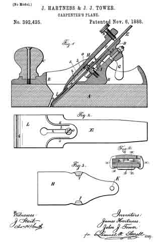
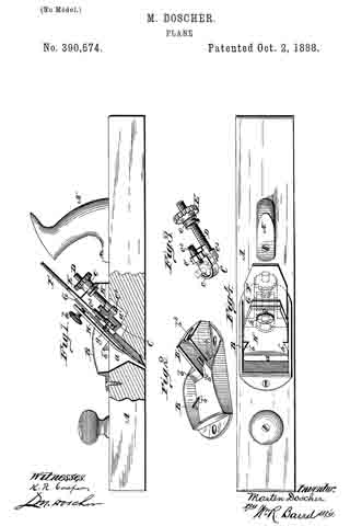
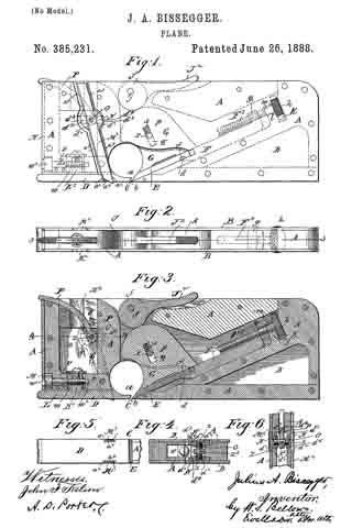
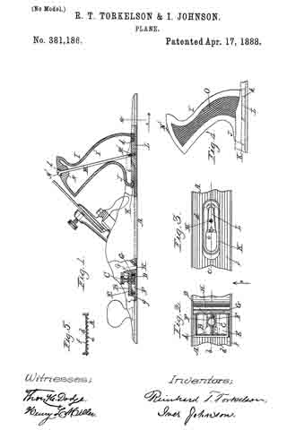
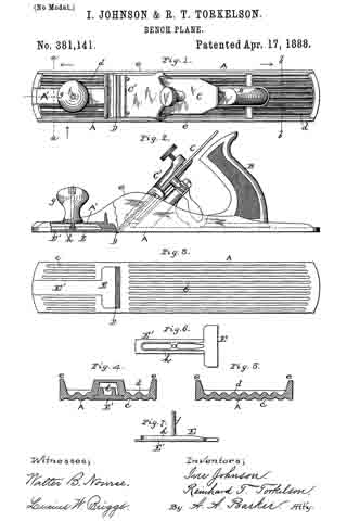
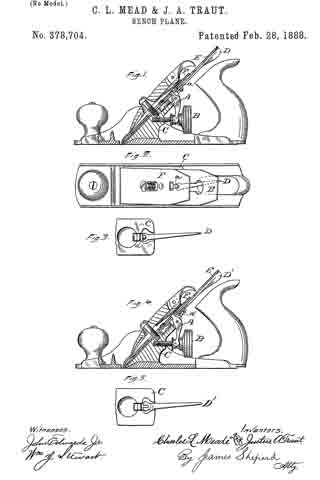
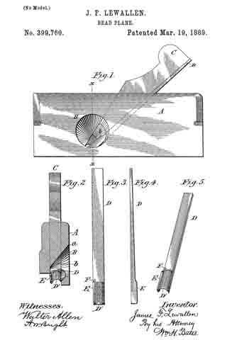
Figure 1 is an elevation of the plane, showing the throat with its bit and key. Fig. 2 is a cross-section on line x x of Fig. 1. Fig. 3 is a plan view of the bit. Fig. 4 is a side elevation thereof; and Fig. 5 is a perspective of the same, showing the flange-cutting lip and the diminishing groove between it and the body of the cutter.

Referring by letter to the said drawings, A indicates a stock, which may be of the form usually employed in bead-planes, having the usual key and bit-seat. At the base of this seat and intersecting the bead is a lateral aperture, B, which is of an annular form and beveled or flaring in its upper portion for the outlet of the shavings, as shown at a.

C indicates the wedge or key for locking the bit in the stock. This wedge, as more fully shown in Fig. 3 of the drawings, is concavely beveled at its lower end-laterally at b, to correspond to the bevel in the lateral aperture B, so as to offer no obstruction to the free discharge of the shavings, and at the same time serve effectively in locking the bit in the stock.

D indicates the bit or cutter, Which is of a peculiar construction, being flat for the greater portion of its length, so as to be snugly seated in the stock. The forward end of this cutter terminates in an edge of substantially ogee form in cross-section, having the semicular upward curvature D’, from one of the longitudinal sides of which rises the upwardly-directed cutting-flange E, divided from the main cutter D’ by a longitudinal groove, F. To this form of cutter I attach importance, as I find in practice that it will cut down into the stock worked upon without tearing up the timber.

By the foregoing construction it will be perceived that the angular part of the cutter will work its way into the wood and form a beading therein to a certain depth before the main part of the bit comes into action. In consequence of this it is essential that the groove be adapted to relieve itself of shavings, for which reason it is made deeper at its cutting-edge than at its terminus in the shank, where it is gradually merged in the flat surface thereof. This arrangement will relieve the groove of the greater quantity of shavings that may be formed therein from the opposing edges of the cutter, and the terminus of the groove when the bit is in the stock will register with the bevel of the key C and facilitate the ejectment of the shavings. By this construction the crimping of the cutting-edge is carried up into the bit-stock, instead of forming merely the outline of the cutting-edge, and the work made by such a bit will have a smoother finish than that ordinarily done.

The throat of the plane with the lower end of the bit-key C forms an oblique cone, the point of its greatest obliquity being toward the month of the plane. This formation insures the ready ejectment of shavings. These pass from the month of the plane into the throat thereof, and, touching against the concavely-beveled end of the key, they pass thence to the surface of the throat, which curls and imparts to them a rotary motion, and finally rapidly ejects them obliquely outward from the stock.

I claim —

In a molding-plane, the combination of the stock having the oblique cone-shaped throat through one cheek thereof, and the bit-key C, having its lower end concavely beveled to conform to the bevel in the throat to form therewith a continuous deflecting discharge-orifice, of a bit having its cutting-edge of substantially ogee form, one side thereof being provided with an upturned cuttingflange, and a groove or depression adjacent thereto, said groove gradually merging in the bit-shank, substantially as described, and for the purpose set forth.

In testimony whereof I affix my signature in presence of two witnesses.

JAMES FRANKLIN LEWALLEN.

Witnesses:
R. T. SHAW,
JAS. W. LOWRY.

No. 399,287 – Gage Attachment For Planes (George H. Russell) (1889)

[paiddownloads id=”446″]399287


UNITED STATES PATENT OFFICE.

_________________

GEORGE H. RUSSELL, OF PITTSFIELD, MASSACHUSETTS.

GAGE ATTACHMENT FOR PLANES.

_________________

SPECIFICATION forming part of Letters Patent No. 399,287, dated March 12, 1889.
Application filed October 27, 1888. Serial No. 289,264. (No model.)

_________________

To all whom it may concern:

Be it known that I, GEORGE H. RUSSELL, a citizen of the United States, residing at Pittsfield, in the county of Berkshire, State of Massachusetts, have invented certain new and useful Improvements in Gage Attachments for Planes, of which the following is a specification, reference being had therein to the accompanying drawings.

This invention has relation to heading or grooving planes, and especially to an adjusting attachment for the same, whereby said plane is adapted for forming beads or grooves of varying widths; and among the prime objects in view are to provide a simply constructed and applied gage that can be easily and quickly adjusted for different-sized grooves or heads, which grooves or beads shall be uniform.

Other objects and advantages of the invention will hereinafter appear, and the novel features thereof will he particularly pointed out in the claim.

Referring to the drawings, Figure l is a perspective of an adjustable attachment for planes constructed in accordance with my invention, and Fig. 2 is a plan of a plane provided with such an attachment.

Like numerals of reference indicate like parts in both the figures of the drawings.

1 represents a longitudinal plate or bar, which may be either straight or curved to fit the side wall of a plane, and which is perfo-
rated at its opposite ends, as at 2, for the passage theirethrough of an adjusting clamping-bolt, 3, the inner ends of which are formed with screw-threads for the reception of thumb-screws 4, and the opposite ends of which are bent at a right-angle, as at 5, so as to embrace the opposite side wall of a plane, 6, whereby said plane may be tightly clamped to the gage.

From the plate 1, and near each of its ends, there project lateral rods 7, which, for a purpose hereinafter apparent, may he provided with a scale.

8 represents the adjusting-bar, which is designed to ride against the side of the work in which the head or groove is being formed, and it is provided with upwardly-disposed opposite arms, 9, terminating in laterally-bored bosses 10, adapted to receive and ride upon the rods 7, and held in position upon said rods by means of set-screws 11, inserted through vertical openings in the bosses, which screws rest upon the rods 7.

By adjusting the gage-bar S upon the rods 7 and securing the same by means of the set-screws 11 it is apparent that beads or grooves of any desired width may be formed, in that, if the plane is adapted for grooving one-fourth inch, to groove one-half inch it is only necessary, after a one-fourth groove has been formed, to set the gage-rod back another quarter-inch and form a second groove, thus increasing indefinitely the capacity of the plane. The device will also he found convenient when a series of boards or posts are to be grooved, each of the grooves or heads to be a predetermined distance from the edge of the work.

By this device uniform work is accomplished.

Having described my invention and its operation, what I claim is —

The herein-described adjnstable gage attachment for planes, consisting of the bar 1, having end perforations, 2, provided with the L-shaped clamping-bolts 3, bent, as at 5, adapted to embrace a plane at its ends, and set-nuts 4, and opposite bars, 7, projecting from the bar 1, and the gage-bar 8, having upwardly-disposed arms 9, terminating in perforated bosses 10, for the reception of the bars 7, and having set-screw 11, substantially as specified.

In testimony whereof I affix my signature in presence of two witnesses.

GEORGE H. RUSSELL.

Witnesses:
JOSEPH MASLEN,
E. M. WOOD.

No. 398,247 – Plane (Henry Fry) (1889)

[paiddownloads id=”445″]398247


UNITED STATES PATENT OFFICE.

_________________

HENRY FRY, OF EUGENE CITY, OREGON.

PLANE.

_________________

SPECIFICATION forming part of Letters Patent No. 398,247, dated February 19, 1889.
Application filed September 13, 1888. Serial No. 285,311. (No model.)

_________________

To all whom it may concern:

Be it known that I, HENRY FRY, a citizen of the United States of America, residing at Eugene City, in the county of Lane and State of Oregon, have invented certain new and useful Improvements in Planes; and I do hereby declare the following to be a full, clear, and exact description of the invention, such as will enable others skilled in the art to which it appertains to make and use the same, reference being had to the accompanying drawings, and to letters or figures of reference marked thereon, which form a part of this specification.

My invention relates to improvements in carpenters’ planes; and it consists in the novel construction and combination of the parts thereof, as will be more fully hereinafter described and claimed.

The object of my invention is to construct a plane wherein the depth of cut of the bit may be adjusted while the plane is in motion without readjusting the bit after the initial setting thereof. I attain this object by the construction illustrated in the accompanying drawings, wherein like letters of reference are used to designate similar parts in the several views, and in which —

Figure 1 is a sectional elevation of a plane, showing my improved construction in connection therewith. Fig. 2 is a detail perspective view of the bit-guard.

S indicates the stock, having the handle s, bit aperture or well s’, and bit and wedge W, all of which are well known in the art.

The improvement consists in securely hinging to the back end of the stock S a movable shoe or bottom, B. To the forward part of the shoe B a stationary flanged socket-nut, E, is secured, the screw-threaded socket thereof projecting upward into and movable in a recess formed in the stock S. An elongated rod, A, having a lower screw-threaded end to engage the screw-threaded socket of nut E and a top projecting knob for engagement by the operator passes through an aperture in the plane-stock. The said rod A immediately under the top knob is provided with a collar, a; and over this collar and fitted into the top surface of the stock is a plate or plates for holding the said collar and screw-rod down and preventing the same rising from the stock.

To prevent the bit from springing backward when striking knots or when cutting deep in hard wood, due to its extended projection from the bottom of the stock to accommodate the improved construction, I provide a guard-casting, F, which is secured to the bottom of the stock adjacent to the bit-end. This guard consists of a horizontal plate, f having screw-holes therein, and an obliquely-arranged plate, f’, integrally formed with its forward end. The oblique plate f’ has its lower edge beveled, and the greater part thereof projects below plate f. When this guard is adjusted in position, the plate f’ thereof bears against the lower end of the bit and prevents the same from springing backward. The part of plate f’ above plate f sinks into the wood or metal of the stock and firmly re-enforces the guard at this point.

The shoe B, working on the hinge and adjusted by the screw-rod A, virtually raises and lowers the plane-bit from and toward the surface planed, causing it to out a light or heavy shaving at the will of the operator, and the adjustment set forth may be readily attained while the plane is in motion, thereby saving the time and labor involved in setting the bits of planes now in use.

In using an iron plane-stock with a wooden shoe, B, two bosses or lugs cast with the back end of the stock would make the hinging of said shoe practicable, and the screw-rod A would then work through the iron stock.

Having thus described my invention, I claim —

1. In a plane,the combination, with a stock having a bit-well therein, of an elongated shoe hinged thereto and solid throughout with the exception of a slot therein for the passage of the bit therethrough, a screw-rod for adjusting said shoe, and a casting composed of a horizontal member secured to the bottom of the stock adjacent to the bit-well, and a front integral member arranged at an angle to said horizontal member, and against which the bit has bearing at its lower end, substantially as described.

2. A plane comprising a, stock with at bit-well, an elongated shoe hinged to the rear end of the stock and having a flanged set-nut secured therein near the front end, a revoluble screw-rod in the stock engaging the set-nut, and a casting, F, having a horizontal member, f, secured to the bottom of the stock, and integral oblique member f’, bearing against the lower end of the bit, substantially as described.

In testimony whereof I aflix my signature in presence of two witnesses.

HENRY FRY.

Witnesses:
W. R. McCORMACK,
JOEL WARE.

No. 395,738 – Spokeshave (Isaac Camier) (1889)

[paiddownloads id=”444″]395738


UNITED STATES PATENT OFFICE.

_________________

ISAAC CAMIER, OF CHICAGO, ILLINOIS.

SPOKESHAVE.

_________________

SPECIFICATION forming part of Letters Patent No. 395,738, dated January 8, 1889.
Application filed September 29, 1887. Serial No. 251,083. (No model.)

_________________

To all whom it may concern:

Be it known I, ISAAC CAMIER, a citizen of the United States, and a resident of Chicago, in the county of Cook and State of Illinois, have invented certain new and useful Improvements in Spokeshaves; and I do hereby declare the following to be a full, clear, and exact description of the same, reference being had to the accompanying drawings, forming a part of this specification, and in which —

Figure 1. is an elevation in direction of arrow, Fig. 2, of a spokeshave constructed in accordance with my invention, and Fig. 2 a transverse section of the same. Fig. 3 is a detached sectional perspective view of the cutter-stock and the clamping-plate for the cutter, illustrating the means for connecting the two together to avoid lateral displacement.

Similar letters of reference indicate like parts in the several views.

This invention relates to that class of wood-working planes known in the art as “spoke-shaves;” arid the objects of the present improvements are to provicle a simple and efficient appliance for adjusting the cutter-bit in accurate parallel alignment with the bearing face or sole of the body or stock of the share, and also to furnish means for firmly clamping and holding the cutter-bit to its adjustment.

To enable others skilled in the art to which my invention appertains to make and use the same, I will now proceed to more fully describe its construction and operation.

Referring to the drawings, A represents the body or stock of the shave, having any usual shape and provided at each side with a wing or handle, B, by which it is manipulated.

C is the cutter bit or blade fitting snugly within the throat of the stock, the sides of said throat forming guiding-slides for the cutter-bit in its adjusting movement. At its upper end the cutter-bit is formed with inturned lips c c, that engage sidewise over a collar or head, d, on the lower end of the adjusting-screw D, which passes through a fixed nut or head, E, at the upper end of the horn or inclined back standard, A’ which in the present improvement forms an integral part of the body or stock A of the shave, and, in addition to carrying the adjusting-screw D, also acts as a bed or rest for the body of the cutter blade or bit, as indicated in Figs. 1 and 2.

The back ot the horn or standard A’ is curved, as shown, to form a continuation of the usual curved heel of the shave, and as so curved and inclined forms no obstruction to the use of the shave on recessed or concaved work.

The clamping-plate G, by which the cutter-bit is clamped in its required adjustment, is secured loosely to the stock by means of an attaching-screw, F, which screws into the stock, as shown, and passes through an elongated hole in the bit C, so that the adjusting movement of the same may take place.

The clamping-plate G, which is of a flat shape, is held from moving in a plane with the cutter-bit, as well as from turning or shifting in such plane, by means of lugs g g, that project in a lateral direction from its side edges and engage or fit snugly in the open-sided recesses a a in the lateral or side walls of the bit-throat, as indicated in Figs. 1 and 3. Such open-sided construction of the recesses a is material to the present construction, in that it permits of the ready introduction of the clamping-plate into operative position by simply dropping said plate into position. With such ready means for attachnient and detachment of the clamping-plate the present construction retains the function of holding the plate G from moving in a plane with the cutter-bit, as above mentioned.

H is a clamping-screw passing through the upper end of the clamping-plate G, with its point resting or bearing upon the cutter bit or blade C, as shown in Fig. 2. With this construction the screw F acts as a fulcrum for the clamping-plate G, so that when its upper end is forced outward by the screw H its lower end will be forced against the blade or bit C, near its cutting-edge, to firmly clamp and hold the same.

By my improved arrangement of parts above described a very substantial and general clainping of the bit is effected in a quick, simple, and easy manner.

I am aware that prior to my invention the cutting-bits of carpenters’ planes had their adjustment effected by means of a screw, and also that clamping-plates operated by a set-screw were employed to hold or clamp the bit to its adjustment. I therefore do not claim either of such constructions, broadly; but

What I do claim as my invention, and desire to secure by Letters Patent, is —

l. The combination, in a spokeshave, of the stock A, having open-sided recesses a a in the lateral walls of the bit-throat, the clamping-plate G, having marginal lugs g g, projecting laterally from its sides and adapted to rest in the recesses a to prevent a movement of the plete G in a, plane with the cutter-bit, the holding-screw F, clamping-screw H, and cutter-bit C, essentially as set forth.

2. The combination, in at spokeshave, of the stock A, having open-sided recesses a a in the lateral walls of its bit-throat, the clamping-plate G, having marginal lugs lugs g g, projecting laterally from its sides and adapted to rest in the recesses a to prevent a movernent of the plate G in a plane with the cutter-bit, the holding-screw F, clamping-screw H, adjusting-screw D, and cutter-bit C, essentially as set forth.

In testimony whereof witness my hand this 17th day of September, A. D. 1887.

ISAAC CAMIER.

In presence of —
JOHN GINOCHIO,
LOUIS BERNERO.

No. 394,411 – Bench-Plane (William Stevenson) (1888)

[paiddownloads id=”443″]394411


UNITED STATES PATENT OFFICE.

_________________

WILLIAM STEVENSON, OF DOUGLAS FLAT, ASSIGNOR OF
ONE-HALF TO JOHN MONTEVERDA, OF STOCKTON, CALIFORNIA.

BENCH-PLANE.

_________________

SPECIFICATION forming part of Letters Patent No. 394,411, dated December 11, 1888.
Application filed April 18, 1888. Serial No. 271,087. (No model.)

_________________

To all whom it may concern:

Be it known that I, WILLIAM STEVENSON, of Douglas Flat, Calaveras county, State of California, have invented an Improvement in Combination-Planes; and I hereby declare the following to be a full, clear, and exact description of the same.

My invention relates to the class of planes in which blades of different character are combined in the same stock; and my invention consists in the novel stock, the double-ended blades and their manner of arrangement, and means for adjusting them in the stock, as I shall hereinafter more fully describe.

The object of my invention is to provide a plane of simple construction, and which, by reason of its different blades, is adapted for several uses.

Referring to the accompanying drawings for a more complete explanation of my invention, Figure 1 is a perspective view of my combination-plane. Fig. 2 is a top view of same. Fig. 3 is a side elevation of the stock, the securing-plate d being removed to show the blade and its operative mechanism.

A is the stock of the plane, having its upper and lower edges made with central longitudinal guides, a, thus dividing it into four working-surfaces, one being on each side of the central guide of each edge. These surfaces in any given stock may be made in the proper shape or contour to suit the several uses intended for that particular combination-tool. In the present instance, in order to illustrate this fully, I have shown two of the surfaces — one on each edge and on the same side of the guides a — as “matching” surfaces — that is, one is for a “tongue” and the other is for a “groove.” The remaining two surfaces I show as a simple “nosing” surface and a “molding” surface. I do not confine myself to them, however, for my invention contemplates the making of any suitable surfaces, the essential feature of the stock in this respect being its construction, providing for any four working-surfaces.

In each side of the stock are made two throat-sockets, B, which are arranged in reversed position with relation to each other, and also in each side of the stock is made a groove-seat, C, opening at each end into one of the working-surfaces and near each end into a throat-socket. Into these grooves C are fitted the blade-guides D, which are secured in place by plates d, let in flush with the sides of the stock and secured thereto by screws d’. Fitted in one side of each of these blade-guides is a rotary pin, e, which carries a pinion, E, the teeth of which project into the guide far enough to engage the rack-teeth of the blades, as I shall presently explain.

Upon the outer end of each pin e (which projects through the securing-plate d) is fixed a lever-arm, F, having at one end a small thumb-piece, f, by which it may readily be turned to turn the pin axially and rotate the pinion, and in the other end said lever-arm carries a set-screw, f’, the lower end of which is made to come in contact with the plate d, whereby the arm may be firmly set in the position to which it may be turned, thus holding the pinion rigidly.

G are the bits. I have shown two. Each is a double-ender-that is to say, a cutting-edge is made on each end. I do not confine myself to the particular shape or character shown on these planes, for they are made to adapt them to the uses intended and corresponding to the working-surfaces of the particular stock they are designed to fit. In this case I have shown a matching-edge on each end of one of the bits, and on the other I have shawn a nosing-edge on one end and a molding-edge on the other end. There are therefore four edges in the set. Each of these bits is formed or provided with rack-teeth g. These bits are fitted through the guides D, so that their rack-teeth are engaged by the pinion E, and their edges extend through the ends of the groove-seats C into proper position along the working-surfaces of the stock. They are made of such a length that when the edge on one end is projected for proper operation in connection with its working-surface the edge on the other end is withdrawn from its working-surface, so as not to be in the way when handling the tool.

The operation is as follows: When I wish to use the grooving-edge, I turn the lever-arm F by the thumb-piece f in a direction and to an extent sufficient to cause the pinion E to project said edge to working position, (the edge on the other end being withdrawn out of the way by the same movement,) and I then fix it in position by setting the screw f’. The operation is the same with any of the other edges.

Having thus described my invention, what I claim as new, and desire to secure by Letters Patent, is —

1. In a combination-plane, a bit having a cutting-edge on each end and having rack-teeth formed on one of its sides, substantially as herein described.

2. In a combination-plane, a stock having a working-surface on its upper and lower edges, in combination with a bit fitted to the stock and having a cutting-edge on each end, and an adjusting device for operating the bit, so that when its cutting-edge on one end is projected into position along its corresponding working-surface the cutting-edge on its other end is withdrawn from its working-surface, substantially as herein described.

3. In a combination-plane, a stock having a working-surface on its upper and lower edges, in combination with a bit fitted to the stock and having a cutting-edge on each end and rack-teeth on its side, and the mechanism for adjusting the bit, as described, consisting of a rotary pin and a pinion carried thereby and engaging the rack-teeth of the bit, substantially as herein described.

4. In a combination-plane, a stock having a working-surface on its upper and lower edges, in combination with a bit fitted to the stock and having a cutting-edge on each end and rack-teeth on its side, and the mechanism for adjusting the bit, as described, and holding it when adjusted, consisting of the rotary pin, the pinion on the pin engaging the rack-teeth of the bit, the lever-arm on the pin, and the set-screw in the lever-arm, substantially as herein described.

5. In a combination-plane, a stock having a working-surface on its upper and lower edges, the bit-guide let into the side of the stock, and the plate screwed to the stock for holding the guide, in combination with a bit fitted in the guide and having a cutting-edge on each end and rack-teeth on its side, and the mechanism tor adjusting the bit, as described, and holding it when adjusted, consisting of the rotary pin in the side of the guide, the pinion on the pin engaging the rack-teeth of the bit, the lever-arm on the outer end of the pin, and the set-screw in the lever-arm, substantially as herein described.

In witness whereof I have hereunto set my hand.

WVILLIAM STEVENSON.

Witnesses:
JOHN W. BATTEN,
ENOS F. FLOYD.

No. 392,425 – Carpenter’s Plane (James Hartness And John J. Tower) (1888)

[paiddownloads id=”442″]392425


UNITED STATES PATENT OFFICE.

_________________

JAMES HARTNESS, OF TORRINGTON, CONNECTICUT, AND JOHN J. TOWER,
OF BROOKLYN, NEW YORK; SAID HARTNESS ASSIGNOR TO SAID TOWER.

CARPENTER’S PLANE.

_________________

SPECIFICATION forming part of Letters Patent No. 392,425, dated November 6, 1888.
Application filed January 14, 1888. Serial No. 260,769. (No model.)

_________________

To all whom it may concern:

Be it known that we, JAMES HARTNESS, of Torrington, in the county of Litchfield and State of Connecticut, and JOHN J. TOWER, of the city of Brooklyn, and State of New York, have invented an Improvement in Carpenters’ Planes, of which the following is a specification.

Carpenters’ planes have been made in which the cutter-iron is held within the stock and is adjusted to cut thicker or thinner shavings by the action of a screw or a lever, and this cutter-iron is clamped to its place by a lever having hooks or lugs that catch behind the portion of the stock or movable cradle upon which the cutter-iron rests. A plane of this character is represented in Letters Patent No. 126,519, granted May 7, 1872, to O. R. Chaplin.

Our present improvement is made for preventing a difliculty that has been experienced in this character of plane-namely, that the cap-iron cannot easily be adjusted and held in the proper position to the cutting-edge of the cutter-iron, because the cap-iron has been attached to the clamp and is moved by and with the clamp when the same is placed upon the cutter-iron, and with planes, especially those having a wooden face, the cutting-edge is within the mortise and cannot be easily seen, and hence the cap-iron may slip down and injure the edge of the cutter, or it may be too far away from the edge of the cutter, and hence not act in the desired manner to break the shavings transversely and prevent the wood splitting.

In the drawings, Figure 1 is a longitudinal section of our improved plane. Fig. 2 is a I detached view of the cap-iron and cutter. Fig. 3 is a separate view of the clamp. Fig. 4 is a section at the line x x, Fig. 1.

The face of the plane and the stock are of any desired character; but our improvement is especially available when the face A of the plane is of wood, to which the metal stock B is attached, having a handle, C, and the inclined bearing D for the cutter-iron E, and this inclined bearing D, is capable of being moved up and down by the action of a screw or lever. We have represented a screw-segment, F, and lever G for adjusting the cutter-iron, as in the aforesaid patent, and the clamp H is made slightly concave upon the under side and provided with hooks or lugs I, that hook behind the inclined bearing D by moving the clamp H down over the cutter-iron, so that the hooks pass along under the bearing D, and there is a screw, K, that acts against the face of the cutter-iron at the upper end of the clamp-lever to force the lower end of such clamp against the capiron L and cutter-iron E.

Instead of connecting the cap-iron L to the clamp H by pins or otherwise, as in said patent, we make the cap-iron L with a longitudinal slot, 2, and with a narrower upper portion, 3, within which such slot is formed, and the lower end, 4, of the cap iron L is of a width corresponding to the width of the cutter-iron E, and the under side of the cap-iron L is slightly concave, as usual in cap-irons, and we make use of a screw, O, passing through the slot 2, for fastening the cap-iron L firmly to the cutter-iron E, and the slot 2 allows for the adjustment of the cap-iron L to bring the end 4 to the proper distance from the cutting-edge of the cutter-iron E. This is done after the cutter has been sharpened and before it is placed in the plane-stock, and this operation in itself is thesame as that which is performed in ordinary carpenters’ planes, and it is usually preferred by carpenters to be able to adjust the cap-iron to the cutter in this manner; but an ordinary cutter-iron and cap-iron are not adapted to the stock and clamp with which our improvement is used, because the hooks I render it necessary to make the cutter-iron narrower at the upper part than in the lower part, and to adapt the cap-iron to the cutter-iron we make the cap-iron narrower, as shown at 3, so that it may extend upwardly the desired distance on the cutter-iron and not be in the way of the hooks I, and we place the screw O with the head above the cap-iron, so that the cutter-iron may rest down flat upon the inclined bearing D; and we may stiffen the upper portion of the cap-iron L by the ribs 5, that are bent up at the edges of the narrower portion, 3, of such cap-iron. The clamp H, being slightly concave on its under side, is adapted to set over the screw o and narrow portion of the cap-iron.

In the ordinary plane-irons the cutter-iron is slotted longitudinally and the screw passes through the slot in the cutter-iron into the cap-iron. This cannot be used in the character of plane upon which our improvement is made, because the screw in that case comes at the back or under side of the cutter-iron.

The ribs 5 upon the cap-iron stiffen the same sufficiently to insure the proper contact of the end 4 of such cap-iron against the surface of the cutter-iron, and the pressure is also increased by the lower end of the clamp-lever H, that is pressed upon the same to hold the cutter in place by the action of the screw K.

The adjustment of the cutter to cut the thicker or thinner shavings is effected in the usual manner without varying the distance between the end it of the cap-iron and the cutting-edge of the cutter-iron E.

We claim as our invention —

1. The combination, with the plane-stock and the inclined bearing D, of the cutter-iron E, the slotted cap-iron L, a screw passing through the slot and attaching the same to the cutter-iron, and the clamp H, made concave to set over the screw and narrow portion of the cap-iron, having hooks I, that catch behind the inclined bearing D, and the clamping-screw K at the upper end of the clamp H for pressing the lower end of the clamp upon the cap-iron and holding the same and the cutter in place, substantially as set forth.

2. The cap-iron L, having a slot, 2, and the ribs 5 at the edges of the narrower portion, 3, of said cap-iron, in combination with the cutter-iron E and the screw O, for connecting the cap-iron to the cutter-iron, and the clamp H, having hooks I, and the screw K, substantially as set forth.

3. The combination, with the cutter-iron E, of the cap-iron L, corresponding in width at its lower end to the width of the cutter and the upper portion, 3, being narrower and provided with a slot, 2, the screw O, for attaching the cap iron to the cutter, the clamp H, having hooks I, and the screw K, and the inclined bearing D and plane-stock, substantially as set forth.

Signed by us this 29th day of December, 1887.

JAMES HARTNESS.
JOHN J. TOWER.

Witnesses:
JOHN W. BROOKS,
W. H. COLE.

No. 390,574 – Plane (Marten Doscher) (1888)

[paiddownloads id=”441″]390574


UNITED STATES PATENT OFFICE.

_________________

MARTEN DOSCHER, OF NEW YORK, N. Y.

PLANE.

_________________

SPECIFICATION forming part of Letters Patent No. 390,574, dated October 2, 1888.
Application filed February 3, 1888. Serial No. 262,855. (No model.)

_________________

To all whom it may concern:

Be it known that I, MARTEN DOSCHER, a citizen of the United States, residing at New York city, State of New York, have invented certain new and useful Improvements in Planes; and I do declare the following to be a full, clear, and exact description of the invention, such as will enable others skilled in the art to which it appertains to make and use the same, reference being had to the accompanying drawings, and to the letters and figures marked thereon, which form part of this specification.

My invention relates to planes; and the novelty consists in the means employed to accurately adjust the double plane-iron without removing it from the stock. All of the planes having such an adjustment of the double plane-iron which have come to my knowledge possess some disadvantage, in that they either require special irons to be made, some work to be done upon the binding-screw, or prevent the usual simple relative adjustment of the plane-bit and cap-iron. In my invention I have sought to remedy these defects by providing a simple device attachable to the head of the binding-screw of the double plane-irons, whereby it can be adjusted in place by means of a screw attached thereto actuated by a milled-headed nut turning in fixed bearings on the plane-stock. By the use of this device an ordinary double plane-iron can always be used with the one stock, and the user and purchaser is not restricted to the special irons made by one manufacturer. It is simple, cheap, and efficient.

In the drawings, in which the same letters refer to the same parts in all the figures, Figure 1 is a vertical medial section and partial elevation of a plane containing my improved device. Fig. 2 is a perspective view of the top plate supporting and guiding the double plane-iron. Fig. 3 is a perspective view of the attachable clutch, and Fig. 4 is a top plan view of the stock containing the device.

A is the plane-stock, having the handle A’ and provided with the slotted opening a a’. On top of the stock and surrounding the opening is a casting, B B’, which I call the “top plate,” and which is securely fastened to the stock by screws or other suitable means. In front the top plate consists of the front wall and two side walls, B, each of which is provided with a wedge-shaped lug, b’, against which the wedge-iron H plays. In the rear the top plate consists of two side walls, B’, each of which terminates in a flange, lb, the upper surface of the walls and flanges serving as a guide and support for the double plane-iron. The rear side walls have each cast on their inside surfaces the lugs b3, serving to guide and support the attachable clutch C, and they have cast between them the rear wall, b2, hollowed out to form a bearing for the groove e of the milled-headed nut E. The cap-iron G and bit-iron F are of any usual form and are slotted and held together in the usual manner by the binding-screw g.

The attachable clutch C is provided with means to receive and firmly hold the head of the screw g. These consist of the semicircular flange c, which provides a broad bearing surface for the periphery of the screw-head, and the set-screw c2, with a slotted head moving in the fixed nut c’. On the under side of the clutch C, and preferably made integral with it, is the adjusting-screw D, operated by the milled-headed nut E, which turns in the bearing b2, formed in the rear wall of the top plate.

The method of using my device is obvious. The plane-bit F and the cap-iron G are iirst fastened together by the binding-screw g. The clutch C is then attached to the head of the screw g, the semicrcular flange c half surrounding the head and it being firmly secured in place by means of the set-screw c2, which has a slotted head at its outer end. The nut E is then placed upon the adjusting-screw D and the whole device is dropped into place in the slotted opening a a’ so that the bottom of the clutch C rests upon the lugs b3. The plane-bit F rests upon the flanges b, and the top surface of the side walls, B’, and the groove e fits into the bearing b2. The nut E is then turned until the double plane-iron is set at the desired position, when the wedge-iron H is put into place and tightened by means of the screw h, and the plane is ready for use.

I may vary the specific means employed to hold securely the head of the binding-screw in the attachable clutch without departing from the principle of my invention; but the means I employ seem to me to be the best and cheapest.

What I claim as new is —

1. In a plane, the combination, with the double plane-iron, of a binding screw the head of which is beneath the said double plane~iron, and an attachable clutch, as C, provided with suitable means for firmly holding the head of said binding-screw and adjusted by means of a set-screw, as D, operated by a nut, E, turning in fixed bearings on the plane stock.

2. I na plane, the attachable clutch C adapted to engage with and firnily hold the head of the binding-screw of the double plane-iron, the said clutch being provided with a top-flanged bearing-surface, as c, a set-screw, as c2, and an adjusting-screw, as D, actuated by a milled-headed nut, E, turning in fixed bearings.

3. In a plane, the top plate, B B’, provided with lugs b’ inside of its front side walls, adapted to serve with the wedge-iron of the plane, with other lugs, b2, inside of its rear side walls, adapted to serve as a guide and support to an attachable clutch, C, engaging the binding-screw of the double plane-iron, and the top surfaces of which walls serve as a guide and support to the said plane-iron, and the top rear wall of which constitutes a fixed bearing, b2, for the nut E, operating the adjusting-screw D of the said attachable clutch.

4. In a plane, the combination, with the double plane-iron and its binding screw, of an attachable clutch, as C, engaging the head of said binding-screw, and the top plate, B B’, having lugs, as b’ and b3, and the rear wall of which constitutes a fixed bearing for the operating-nut E of the adjusting-screw D of said attachable clutch, with said nut E, and adjusting-screw D, as set forth.

5. In combination with the binding-screw of a double plane-iron, whereof the plane-bit is slotted longitudinally and the cap-iron is provided with a threaded opening for the reception of said binding-screw, an attachable clutch, as C, placed beneath the double plane-iron, provided with suitable means for firmly holding the head of said binding-screw and other means for adjustment of the said clutch operated by the nut E, turning in fixed bearings.

In testimony whereof I affix my signature in presence of two witnesses.

MARTEN DOSCHER.

Witnesses:
JOHN H. COCHRAN,
L. M. DOSCHER.

No. 386,509 – Bench-Plane (Justus A. Traut) (1888)

[paiddownloads id=”440″]386509


UNITED STATES PATENT OFFICE.

_________________

JUSTUS A. TRAUT, OF NEW BRITAIN, CONNECTICUT, ASSIGNOR TO
THE STANLEY RULE AND LEVEL COMPANY, OF SAME PLACE.

BENCH-PLANE.

_________________

SPECIFICATION forming part of Letters Patent No. 386,509, dated July 24, 1888.
Application filed April 17, 1888. Serial No. 270,273. (No model.)

_________________

To all whom it may concern:

Be it known that I, JUSTUS A. TRAUT, a citizen of the United States, residing at New Britain, in the county of Hartford and State of Connecticut, have invented a certain new and useful Improvement in Bench-Planes, which improvement is fully set forth and described in the following specification.

Reference is also made to the sheet of drawings annexed hereto, in which Figure 1 is a side elevation of a plane having my improvement embodied therein. Fig. 2 is a sectional detail view of the same on line x x of Fig. 1, and Fig. 3 is a like view with the cutting-bit attached. Fig. 4 is a sectional detailed view on a central longitudinal line. Fig. 5 is a detached perspective view of the lever by means of which the cutting-bit is rocked or adjusted laterally, as hereinafter explained.

The class of planes to which my invention relates is that in which the cutting-bit may be adjusted laterally relative to its seat for the purpose of bringing the cutting-edge of said bit parallel with the throat, or, in other words, square with the plane-stock. A familiar type of said class is shown and fully described in my Patents No. 306,877 issued October 21, 1884, and No. 376,455, January 17, 1888, to which patents reference is hereby made.

The object of my present invention is to improve the construction of the lever employed to adjust the bit laterally, so that said device may work easier and with less friction than heretofore. To produce this desired result I have secured to the bit-engaging end of the adj usting-lever an anti-frictional disk that partially rotates on its axial pivot, as I will proceed to describe.

The letter B denotes the cutting-bit; A, the seat provided for said bit in the so-called “frog” of the plane, and C the cap-iron.

a indicates my new form of lever provided to adjust the bit in a lateral direction. Said lever is perforated, as at a’, to slip over a pin, a2, near the rear end of the bit-seat A, said pin forming the fulcrum on which the lever swings. The bit-seat is recessed, as atb, to receive said lever, said recess being of such depth that the lever may move freely between the bit and frog when the several parts are assembled for use. The lower or short arm of lever a has pivoted to its bit-engaging side a disk, c, that may rotate freely on its pivot. This disk, when the parts are assembled, projects upward into the bit slot d. (See Figs. 3 and 4.)

When it is desired to adjust the bit to square it with the plane-stock, the free end of lever a is swung to one side — as, for example, in Fig. 3 — which action moves the short arm of said lever in the opposite direction, and the disk c carries with or before it the bit B. During this adjusting operation disk c partially revolves on its axial pivot, and so reduces in a considerable degree the friction of the engaging parts.

My device, as described, may be applied to planes of this class without any material changes, and does not add to the cost of such tools.

I claim as my invention —

In combination with the stock and bit of a plane, a lever for laterally adjusting said bit, and the rotary disk pivoted on the shorter arm of said lever and engaging the longitudinal slot of said bit, substantially as described, and for the purpose specified.

JUSTUS A. TRAUT.

Witnesses:
HENRY S. WALTER,
H. C. HINE.

No. 385,231 – Plane (Julius Armin Bissegger) (1888)

[paiddownloads id=”439″]385231


UNITED STATES PATENT OFFICE.

_________________

JULIUS ARMIN BISSEGGER, OF NEW YORK, N. Y.

PLANE.

_________________

SPECIFICATION forming part of Letters Patent No. 385,231, dated June 26, 1888.
Application filed November 8, 1887. Serial No. 254,632. (No model.)

_________________

To all whom it may concern:

Be it known that I, JULIUS ARMIN BISSEGGER, a citizen of the United States of America, and a resident of the city, county, and State of New York, have invented certain new and useful Improvements in Planes, of which the following is a specification.

The present invention relates to planes, and particularly to rabbet-planes, the object whereof being to insure accuracy in the operation thereof, and otherwise increased efficiency therein; and it consists in the construction and combination of parts, all substantially as will be hereinafter fully described, and pointed out in the claims.

In the accompanying sheet of drawings, Figure 1 is a side view of a plane comprising the present invention. Fig. 2 is a plan view of same. Fig. 3 is a central vertical section of the plane on line 3 3 of Fig. 2. Fig. 4 is a horizontal sectional view in detail on line 4 4, Fig. 3. Fig. 5 is a plan view of a portion of the face of the plane. Fig. 6 is a section on line 6 6, Fig. 3.

In the drawings, A represents the plane body or stock, having plates B at each side thereof, covering the whole area thereof, except at the portion a, at and over the plane-throat C.

D is a throat-plate adapted to be movable, as hereinafter explained, and E is the plane-iron, having cutting-edge b, as usual in planes.

F is the plane-iron holder, which has a transverse rib, d, corresponding and closely fitting a transverse groove, f, in the plane-iron. The upper end of the plane-iron holder is provided with a right-angled lug or ear, g, through the inner screw-thread of which a screw-threaded bolt, F2, engages. This bolt F2 has a head, h, which lies in a recess, K, at the rear of a lug, Z, in the casting, and the shank of the screw-bolt F2 plays loosely through a hole, m, therefor in said lug l. The head of the bolt F2 is milled, and at each side projects through apertures K in the side plates, B, of the plane-stock,and may be conveniently turned by the hand to project or withdraw the edge of the plane-iron at the throat, as is plain.

G is a block which bears on the upper side of the plane-iron, and it has a tongue, p, projecting upwardly in the inner recess of the plane-stock, through which is a slot, q, having a direction perpendicular to the plane-iron E, through which slot is passed a stationary pin, r, extending from side to side of the plane-stock. Above the stationary pin r, and bearing on and between it and the upper wall of the slot q, is a spiral spring, s, which tends to force the block G upwardly away from the plane-iron. Resting over and upon the edge of block G is a cam-disk, J, pivotally hung in the plane-stock, as at j, having a handle-arm, J2, and all so arranged that when said arm is swung downwardly, as shown, it will of itself so remain until swung upwardly from the plane-iron E, allowing same, through the turning of the screw-bolt, to be altered in its projection, or to be removed, as desired.

The throat-plate D has its outer face of the same width as the face of the plane-stock, and it has a tongue or upward projection, K2, extending into the open space w, formed in the stock A. Extending through the part v of the stock is a screw-threaded bolt, L, which engages the female screw-threads of the upward extension K2 of the throat-plate D, and the end of the screw-bolt L is supported in a socket, w2, in the part x of the stock, as seen in Fig. 3, said bolt being prevented from longitudinal movement in one direction by the end of socket w2, and in the other direction by its abutment against the plate M, secured on the end of the plane-stock. The plate M, however, has a hole, w3, of diameter smaller than that of the bolt L, opposite such head, through which a screwdriver or wrench may be inserted to engage with the screw-slot. By turning the screw-bolt in one direction the throat-plate is moved toward the plane-iron to contract the opening or throat C, and when turned in the other direction the throat-opening is thus widened.

M2 M2 are pointed blades or groovers which are located at opposite sides of the plane in longitudinal lines coincident with the outer edges or corners of the plane-iron, as shown in plan view, Fig. 5, in advance of the plane iron. These blades are adapted and intended to be projected a distance beyond the face of the plane as great at least as the projection beyond the face of the plane of the plane-iron, and in the operation ofthe plane, in the usual manner, the blades M2 M2 form parallel grooves or demarkations, exactly within and between which the cutting plane-iron E follows and cuts the shaving.

The grooving-blades M’ M” extend through dovetailed grooves a2 in the throat-plate, and are beveled or dovetailed on their edges, fitting the dovetailed grooves in the throat-plate. There is also a clamp, N, for receiving each grooving-blade, having inner dovetailed grooves, d2, corresponding to the dovetail shape of the blades M2. The clamps N2 are adapted to be drawn inwardly, carrying the blades M2 therewith in a transverse line of the plane and firmly against the stock at its portion a3 above and below the clamp N, and inwardly against the inner wall, a4, of the grooves in the throat~plate, and this inward bind of the grooving-blades is secured by the screw-pin O, differentially threaded at its opposite end portions z, having intermediate of its length a squared portion, z2, by which a permanent or other wrench-arm, P, engages, the turning of which screw-pin in one direction causes the clamps N to move inwardly, and the turning of the screw-pin in the opposite direction causing the clamps to move outwardly for maintaining the bind of the blades M2 against the side of the stock and throat-plate, or for releasing such bind to permit the adjustment or release of the grooving-blades.

The opposed sides of the stock A. are provided with horizontal ways or grooves d3, in which play projections d4 of the clamp N, permitting the clamps to move longitudinally of the plane-stock, as the blades are so carried when the throaaplate D is moved longitudinally either to widen or contract the throat.

Having thus described my invention, what I claim, and desire to secure by Letters Patent, is —

1. The combination, with the plane-stock having the pin r, the cam J, and the plane-iron, of the block G between said cam and plane-iron, having slot q, substantially as described.

2. The combination, with the plane-stock having the pin r, the cam J, and the plane-iron, of the block G between said cam and plane-iron, having slot q, and spring s, substantially as and for the purpose described.

3. The combination, with the recessed plane-stock having lug m, screw F2, ribbed plane-holder F, having lug g, notched plane-iron E, and pivoted cam J, having handle J2, of block G between said cam and plane-iron, having slot q, and spring s, substantially as and for the purpose described.

4. The combination, with a plane-stock having vertically-arranged recesses a3 a3, and the horizontal grooves d3 d3, of the clamping-blocks N N, having dovetailed sockets, inwardly-extending projections d4, and threaded screw-receiving holes, the right and left threaded screw having the intermediate projecting lever, P, and grooving-knives having dovetailed edges bearing in said socketed block, substantially as described, for the purposes set forth.

In testimony that I claim the foregoing as my invention I have signed my name in presence of two witnesses.

JULIUS ARMIN BISSEGGER.

Witnesses:
WM. SEARS BELLOWS,
CHAS. S. SENTELL.

No. 384,844 – Plane (Andre S. Haynes) (1888)

[paiddownloads id=”438″]384844


UNITED STATES PATENT OFFICE.

_________________

ANDRE S. HAYNES, OF ROME, NEW YORK.

PLANE.

_________________

SPECIFICATION forming part of Letters Patent No. 384,844, dated June 19, 1888.
Application filed March 13, 1888. Serial No. 267,076. (No model.)

_________________

To all whom it may concern:

Be it known that I, ANDRE S. HAYNES, of Rome, in the county of Oneida and State of New York, have invented certain new and useful Improvements in Planes; and I do hereby declare the following to be a full, clear, and exact description of the invention, such as will enable others skilled in the art to which it pertains to make and use it, reference being had to the accompanying drawing, which forms part of this specification.

My invention relates to an improvement in planes; and it consists in, first, the combination of the frame or body of the plane, a pivoted spring-actuated cutter-holder, a connecting-rod, and a lever which is used in connection with the handle for making the cutter-holder movable; second, the combination of the body or frame of the plane, a pivoted spring-actuated cutter-holder, a connecting-rod, a pivoted lever used in connection with the stationary handle, and a set-screw for regulating the distance the handle shall move the cutter, as will be more fully described hereinafter.

The object of my invention is to produce a plane in which the force used in propelling the plane forward is made to bring the cutter into position for operation, but which cutter, as soon as the grasp of the hand is relaxed as the plane is drawn backward, will move upward in the slot in the body or frame, so that its edge will not drag along upon the lumber, and to make the lever used in connection with the handle adjustable, so that the cutter can be held rigidly in position or the distance that it shall move upward out of contact with the lumber be regulated.

The accompanying drawing represents a vertical section of a plane which embodies my invention.

A represents an ordinary metallic plane body or frame,which is provided with the handle X at its front end and with the handle D near its rear one, and which handles are secured to the frame in any suitable manner. Pivoted upon the lower end of the handle D, at F, is the lever E,which forms a portion of the handle and lever by means of which the cutter is moved into position for work. In the upper end of the lever E is made a recess, O, in which the head of the set-screw N is made to catch. This screw N passes through the lever E into the handle D and serves to regulate the distance the lever E shall move. When the screw N is screwed up tightly, so as to force the lever E in contact with the handle D, the cutter is held in position so that it has no movement whatever, and then operates like an ordinary plane. When the screw N is unscrewed a short distance, the lever E is forced backward by means of the springs M and the connecting-rod G, and thus regulates the distance that the cutter shall be moved upward in the slot in the bottom of the frame or body.

Pivoted to the lower end of the lever E at the point H is the rod G, which is pivoted at its front end by the pin I to the lower portion of the cutter-holder B. This cutter-holder is pivoted upon the frame or body A at C, and has connected to it a spring, M, upon each side of the body or frame, and which springs serve to hold the lower end of the cutter-holder B and the cutter J in a raised position in relation to the slot P. The devices for securing the cutter to the cutter-holder B are old, and hence need not be more fully described in this connection. This lever E is first moved so as to depress the lower end of the cutter-holder, and then the cutter is adjusted into an operative position. When the lever E is released, the spring M instantly raises the lower end of the cutter and the cutter-holder upward, so that the lower edge of the cutter will be raised above the piece of timber that is being dressed. In order to regulate the distance the cutter-holder and cutter shall move downward, suitable stops, Q, are formed upon the body A, and corresponding stops, R, formed upon the back of the cutter-holder. These stops prevent the lower edge of the cutter from ever being forced down below a certain point.

When the handle D and lever E are taken hold of and the plane is forced forward, the connecting-rod G causes the cutter-holder B to turn upon its pivots C, and thus move the lower edge of the cutter downward through the slot P into an operative position. When the pressure or grasp of the hand is released in drawing the plane backward, the springs M instantly raise the lower end of the cutter-holder so that the lower edge of the cutter is raised in the slot P, so as not to come in contact with the lumber while the plane is being drawn backward, and thus prevent the edge of the cutter from becoming dulled, and to make the operation of drawing the plane back easier. As above stated, when it is not desired that the cutter-holder and cutter shall have any movement, it is only necessary to tighten the screw N, and the lower end of the lever E will move the rod G endwise until the stops upon the rear side of the cutter-holder strike against the stops on the body A, when the plane will act like an ordinary one.

Having thus described my invention, I claim —

1. The combination with the body or frame, of a movable cutter-holder, the cutter secured thereto, a connecting-rod, the handle, and a lever loosely connected to both the rod and the handle and adapted to be grasped with the handle, substantially as shown.

2. The combination of the body or frame of the plane, with the pivoted spring-actuated cutter-holder, the cutter secured thereto, a connecting-rod, and a pivoted lever which is operated by the forward pressure of the hand in moving the plane forward, substantially as described.

3. The combination of the stationary handle D, the lever E, pivoted thereon, the adjusting setscrew N, the connecting-rod, the pivoted spring-actuated holder, and the cutter, substantially as set forth.

4. The combination of the body or frame of the plane, provided with stops, a spring-actuated cutter-holder provided with stops near its lower end, the cutter secured to the holder, the connecting-rod fastened to the lower end of the cutter-holder, the stationary handle, the lever pivoted upon the handle and connected at its lower end to the connecting rod, and an adjusting device for regulating the amount of movement which shall be given to the cutter, substantially as specified.

5. The combination, in a plane, of a cutter-holder having a cutter secured thereto, a spring-actuated lever connected to the handle, and a rod which connects the lever and the cutter-holder together, whereby the cutter is depressed by the lever as the plane is forced forward and is returned to position by the spring as the plane is drawn backward, substantially as specified.

In testimony whereof I affix my signature in presence of two witnesses.

ANDRE S. HAYNES.

Witnesses:
P. R. HUGGINS,
K. S. PUTNAM.

No. 383,590 – Spokeshave (James H. Polhemus And Bengamin F. Polhemus) (1888)

[paiddownloads id=”437″]383590


UNITED STATES PATENT OFFICE.

_________________

JAMES H. POLHEMUS AND BENGAMIN F. POLHEMUS, OF BROOKLYN, NEW YORK.

SPOKESHAVE.

_________________

SPECIFICATION forming part of Letters Patent No. 383,590, dated May 29, 1888.
Application filed January 20, 1888. Serial No. 261,377. (No model.)

_________________

To all whom it may concern:

Be it known that we, JAMES H. POLHEMUS and BENGAMIN F. POLHEMUS, of Brooklyn, in the county of Kings and State of New York, have invented a new and Improved Spoke-shave, of which the following is a full, clear, and exact description.

Our invention relates to spokeshaves, and has for its object to provide a tool capable of use as readily in curves of small radius as upon a flat surface, and, further, to produce an improvement upon the spokeshave for which Letters Patent No. 368,003 were granted to us August 9, 1887.

The invention consists in the construction and combination of the several parts, as will be hereinafter fully set forth, and pointed out in the claims.

Reference is to be had to the accompanying drawings, forming a part of this specification, in which similar letters of reference indicate corresponding parts in all the views.

Figure 1 is a plan view of the complete spoke-shave. Fig. 2 is a transverse section on line x x of Fig. 1. Fig. 3 is a perspective view of the cap-plate. Fig. 4 is a perspective view of the cutting-blade, and Fig. 5 is a perspective view of the cutting-blade and attached adjusting-plate. Fig. 6 is a perspective view of the adjusting-screw.

At each side of the central portion of the tool A, having the ordinary handles, a, and transversely the said tool, vertical ears B are formed, provided near their upper edge with a segmental slot, b, and a parallel integral offset, C, upon the inner face of the base.

In the body D of the tool, intervening the ears B, a central recess, d, is produced, and centrally and transversely the recess a threaded rod, E, is extended, provided with a milled head, e, at one end. One end of the transverse screw-rod is made to turn in an aperture, e’, produced horizontally in the forward wall of the body-recess d, the other end of said rod being journaled in the rear wall of said recess with the head e outside.

A rectangular nut, F, is made to travel in the recess d upon the threaded rod E, and upon said rod E, a short distance from the head, a collar, f, is formed, whereby the rod is prevented from having lateral play in its bearings.

A knife, G, having a central slot, g, is made to slide on the body-surface D over the recess d between the transverse offsets C of the ears B. The knife, as shown in Fig. 1, is also provided with a small rectangular slot, h, to the rear of the main slot g, which slot h is adapted to receive the traveling nut F, whereby, when the screw-rod E is manipulated, the knife is moved backward or forward across the face of the body. In the rear central edge of the knife a slot, h’, is cut, purposed to permit the free action of the screw-collar f’, and also to afford a convenient means for oiling the rear bearing of the said screw-rod.

An adjusting-plate, H, is provided for the knife of essentially the same shape, adapted to cover the upper surface, which adjusting-plate is beveled upon the outer edge and fitted with a central slot, H’, exposing the slot h in the knife, and at each side of the central slot, H’, smaller slots, k’, are produced. The plate H is adjustably held upon the knife by means of screws o, passed through the aforesaid side slots, k’, and entered into the knife, as illustrated in Fig. 5.

The purpose of the plate H is to regulate the delivery of the shaving and cause the tool to cut as well across the grain as with it. In cutting across the grain the plate is slid a proper distance back of the knife-edge, as shown in Fig. 5. A cap-plate, K, is provided adapted to rest upon and partially cover the knife G, which plate rests against the inner surface of the transverse offsets C at the ends, being provided with end shoulders, k, purposed to bear against the rear ends of the said offsets and limit the forward motion of the cap-plate.

Centrally the cap-plate K, near the forward edge, an elongated slot, m, is produced, adapted to register with the slot g in the knife and slot H’ in the adjusting-plate, and through the forward end of the registering slots m, g, and H’ a set-screw, M, is passed into a suitable threaded aperture in the body. At each side of the slot m, a smaller slot, m3, is produced, purposed to accommodate the heads of the screws o.

In operation the set-screw is loosened and the head of the threaded rod E is manipulated to the right or left, accordingly as the knife is to be moved backward or forward. When the proper adjustment has been found, the set-screw is screwed down, the opening in having previously been closed by means of a hinged cover, m’, to keep out the dust, and the said set-screw thereby retains the cover in place, as shown in Fig. 2, and prevents any movement of either the cap-plate or knife.

A guide, M’ consisting of the longitudinal bar m2, having a flat under surface and more or less rounded corners, and provided with integral arms at right angles thereto, is adjustably held within the ears B by thumb-screw N, entering the slot D in said ears, and also the said arms of the guide at their ends. When the guide M’ is thus positioned, the flat under surface thereof is normally in the same horizontal plane with the under flat surface of the body D. A space is, however, made to intervene the opposing edges of the said body D and the guide.

It will be observed that by reason of the slots k’ in the adjusting-plate and the screws o all strain is removed from the clamping-screw M and the knife insured when manipulated a direct throw free from lateral vibration.

Having thus described our invention, what we claim as new, and desire to secure by Letters Patent, is —

1. In a spokeshave, the combination, with the body having a recess in the upper face, a threaded rod held to turn in the body-recess, and a rectangular nut traveling upon said rod in said recess, of a blade adapted to slide upon the body above the recess, having a slot cut therein to receive the nut, an adjusting-plate held to slide upon the knife, provided with guide-slots and guide-screws, a cap~plate resting upon said blade, slotted to accommodate the guide-screws, and a set-screw passing through the cap-plate and blade into the body, substantially as shown and described.

2. In a spokeshave, the combination, with the body having a recess in the upper face, a threaded rod held to turn transversely and horizontally in said body-recess and provided with a head upon the outer end, and a rectangular nut traveling upon said rod in said recess, of a blade adapted to slide upon the body above the recess, having a series of central slots cut therein, one of which is adapted to receive the nut, an adjusting-plate held to slide upon the knife, provided with a central slot, side guide-slots, and guide-screws, a cap-plate resting upon the said blade, provided with shoulders at opposite ends engaging the body, and a central slot and side slots accommodating the guide-screws, and a set-screw passing through the slot of the cap-plate, the central slot of the adjusting-plate, and through the registering slot in the knife into the body, substantially as shown and described.

JAMES H. POLHEMIUS.
BENGAMIN F. POLHEMUS.

Witnesses:
J. F. ACKER, Jr.,
C. SEDGWICK.

No. 383,234 – Bench-Plane (Thomas H. B. Millsap) (1888)

[paiddownloads id=”436″]383234


UNITED STATES PATENT OFFICE.

_________________

THOMAS H. B. MILLSAP, OF HARPER, KANSAS.

BENCH-PLANE.

_________________

SPECIFICATION forming part of Letters Patent No. 383,234, dated May 22, 1888.
Application filed April 13, 1887. Serial No. 234,678. (No model.)

_________________

To all whom it may concern:

Be it known that I, THOMAS H. B. MILLSAP, of Harper, in the county of Harper and State of Kansas, have invented a certain new and useful Improvement in Bench-Planes, of which the following is a full, clear, and exact description, reference being had to the accompanying drawings, forming part of this specification, and in which —

Fig. I is a perspective view of a bench-plane with my improved attachments, showing the action of the friction-spring side wedges in front and the pivoted adjustable abutment-clamp behind. Fig. II is a perspective view of one of the spring-wedges, showing its friction-surface for engagement with the abutment-shoulder of the stock. Fig. III is a longitudinal transverse section showing the bit-iron and the break-iron secured thereto, clamped intheirbcd in thestock by the spring-wedge and the adjustable abutting-clamp. Fig. IV is a detail side view, showing the adjustable abutment screw-clamp thrown back on its pivot in its inoperative position, and Fig. V is a modification of the friction spring adapted for use with heavy jointer-planes, &c. , having at its upper end an elongated bearing-surface that engages with the bit or break iron and a solid tapping-head, by striking which it is driven home to tighten the iron and back again to release it.

My invention relates to devices for adjusting and securing benchplane irons; and the invention consists in features of novelty hereinafter fully described, and pointed out in the claims.

Referring to the drawings, in which similar distinguishing figures indicate like parts in all the views, 1 represents the plane-stock, 2 the bit-iron, 3 the break-iron, which is adjustably secured to the bit-iron by the usual means, consisting of the coupling-screw 4, that works in the elongated slots 5 of the bit-iron and screws into the break-iron at 6.

7 is the inclined bed on which the bit-iron rests, and 8 is the elongated channe-groove in said bed to give adjustable room for the head of the screw 4.

9 are the friction-spring side wedges that conjointly press against the abutment-shoulders 10 of the stock and the bit or break iron. These springs are preferably made of good steel, and are looped around at top to provide circular handles 11 and curved upward onthe under side, both next the handles and the points 12, and thus form a semi-elliptic spring, which is flattened between said curves to present the friction surfaces 13 on their upper sides, which engage with the abutment-shoulders of the stock. The said friction-surfaces are roughened to give them grip-holds of the stock to prevent their slipping. (See Fig. I, II, and III.)

A rnodification of the springs is shown in Fig. V, and is intended for use with jointers and other large planes. The point, friction-surface, and arched curve are similar in these spring-wedge to those already described, but instead of the circular handle with which the former are provided, these are furnished at their upper ends with elongated bearing-surfaces 14 on their under sides that are seated on the bit or break iron, and they have also solid tapping heads 15, by striking which they are driven home to tighten the iron. and back again to loosen it.

16 is the adjustable abutting pedestal, which is connected by a pivot pin, 17, to the strap-hinge 18, that is secured to the stock. The pedestal is furnished with points 19 at its base, which points seat themselves in the stock under the pressure to which they are exposed, and with the re enforcement of the hinge by which the pedestal has pivotal connection with the stock is provided a firm vantage-ground, from which the abutting device connected with said pedestal can work.

20 is the thumb-screw whose screw-threaded end engages in the socket-screw 21 in the pedestal, and with its center point 23, which should be of hard tempered steel, and the said pedestal forms the abutting device to adjustably back the plane iron. The thumb-screw is operated by the friction disk 22, that is rigidly secured thereto.

The means of operating the device is as follows: The plane iron and break iron having been rightly adjusted and coupled in the usual manner and laid in their bed, the center point of the thumb-screw may be brought into close proximity with the back of the plane-iron by turning the friction-disk. The friction-spring side wedges are then driven down between the abutment-shoulders of the stock and the bit or break iron, and the abutting thumb-screw is turned to adjust the backing of the iron. The thumb-screw can be turned until its center point is exactly on a line with the inclined bed that the iron occupies in the stock, or it may, when preferred, be projected upward sufficiently to raise the upper end of theiron from its bed. In the latter position it furnishes a lively cutting-grip to the edge of the plane-iron, as the iron having play between the foot of the inclined bed to the point of contact of the abutment-screw gives a spring action to the edge not otherwise attainable. In either case, whether the iron is sprung above from its bed or not,the abutment screw, backing the iron at a point much higher than the usual backing against the inclined bed of the stock, furnishes a much firmer hold and efficient leverage on the iron than can be attained bythe shorter backing of the stock-bed. This feature is of special advantage in dressing cross-grained boards or timber, where the increased leverage that it gives to the hold of the iron prevents the trembling of the same.

Another, and it may be equally important, feature in the device is, that it leaves an open unobstructed vent for the escape of the shavings, which, with the wooden wedge hitherto used, that stretches across the whole slot of the stock, often becomes choked by the wedge, which blocks their ascent, and this causes the plane to choke.

The modification shown in Fig. V provides spring friction-wedges especially adapted for use in jointers and other heavy planes. It will be seen that except for the upper parts of the wedges they are counterparts of those shown in the other figures; but to adapt them to the heavy work which they are required to perform they are furnished at their upper ends with elongated bearing-surfaces on their under side, that are seated on the bit or break iron when the wedge is driven home, and, instead of the circular open head of the other wedges, have a solid head adapted to be tapped by a hammer or mallet when either driven home or released from its hold.

I claim as my invention —

1. In abench-plane, the combination, with the bit-iron and break-iron secured thereto, of spring-friction side wedges and pivoted abutment-pedestal having a center-pointed thumb screw adapted to adjust and secure said bit and break iron, substantially as set forth.

2. In a bench-plane, the combination, with the bit-iron, break-iron, and the stock having abutment-shoulders, of friction-wedges having spring-arches fiattened at their apices and adapted to engage with the abutment-shoulders of the stock, and an abutment-pedestal having a center-pointed thumb-screw, which, in conjunction with the said wedges, is adapted to adjust and hold the plane-irons to their place in the stock, substantially as set forth.

3. The combination, with the stock having abutment-shoulders and the bit and break iron, of a pivoted abutment-pedestal having a thumb screw adapted to engage the bit-iron, and spring-wedges engaging between the plane-irons and the abutment shoulders of the stock, said wedges being so arranged that there will be no intrusion on the chamber of the stock, to allow free vent for the shavings, substantially as set forth.

4. The combination, with the stock, bit and brake irons, of spring friction-wedges adapted to clamp the bit and break irons in front, a pivoted abutment-pedestal having a pointed projection adapted to engage the stock, anda pointed thumb-screw engaging in the end of said pedestal and adapted to adjust their backing and lengthen the lever-hold of said irons in the bed of the stock, and thereby steady their cutting action, substantially as set forth.

5. The combination, with the stock and its abutment-shoulders and the bit and break irons, of spring friction-wedges engaging between the front of the irons and the abutment-shoulders of the stock, leaving free vent between them for the escape of shavings, and a pivoted abutment-pedestal having a center-pointed rotary screw adjustable as an abutting support to the back of the irons, substantially as set forth.

THOMAS H. B. MILLSAP.

In presence of —
A. W. SKINNER,
F. W. HAWSER.

No. 381,186 – Plane (Reinhard T. Torkelson And Iver Johnson) (1888)

[paiddownloads id=”435″]381186


UNITED STATES PATENT OFFICE.

_________________

REINHARD T. TORKELSON AND IVER JOHNSON, OF WORCESTER, MASSACHUSETTS.

PLANE.

_________________

SPECIFICATION forming part of Letters Patent No. 381,186, dated April 17, 1888.
Application filed September 14, 1885. Serial No. 177,099. (No model.)

_________________

To all whom it may concern:

Be it known that we, REINHARD T. TORKELSON and IVER JOHNSON, both of the city and county of Worcester, and Commonwealth of Massachusetts, have invented certain new and useful Improvements in Planes; and we do hereby declare that the following is a full, clear, and exact description of the same, reference being had to the accompanying drawings, forming a part of this specification, in which —

Figure 1 represents a vertical section through the ends of the plane on line b c, Figs. 2 and 3; Fig. 2, a top or plan view of the front of the plane; Fig. 3, a top or plan view of the rear section of the plane with the handle removed; Fig. 4, a side view of the handle and a small section of the plane-bed; and Fig. 5 represents a cross-section on line a, Fig. 1, looking in the direction of arrow 1.

To enable those skilled in the art to which our invention belongs to make and use the same, we will proceed to describe it more in detail, the nature of which consists, first, in certain improvements in the construction of an adjustable throat device; second, in improvements in the construction, whereby the handle may be detachably fastened to the bed; and, third, in an improved plane-bed, all as will be hereinafter more fully described.

In the drawings, A represents the bed of the plane,which is provided with corrugations d, the lower edges, e, of which are flat, and upon its upper side with round corrugations f. By this construction of the bed it can be made very light, while at the same time it is very stiff, thus utilizing in material, while at the same time rendering it light, and thus requiring less labor to operate it.

B represents an adjustable throat arranged upon the upper side of the plane-bed, through which a thumb-screw, C, passes into a set-nut, D. This nut works between two dovetail flanges, F F, (shown in full lines, Fig. 1, and dotted lines, Fig. 2,) the sides of the nut being made dovetailing to fit, and, consequently, while the nut can be moved back and forth it cannot be raised out of place until screw C and throat B are removed.

The body part E of the adjustable throat rests upon upright flanges g, (shown in full lines, Fig. 1, and dotted lines, Fig. 2,) and between the side flanges ofthe plane-bed F F. A forward projection, G, fits into the throat H, and which projection can be slid back and forth, as indicated in full and dotted lines, Fig. 1, and quickly adjusted, by means of the thumb-screw G, to give any desired opening to the throat H. This arrangement also leaves the under side of the bed of the plane smooth, thereby obviating the objections to the adjustable throats heretofore fitted to work on the under side of the plane.

I represents the handle of the plane, made of vulcanized india-rubber. It is made hollow, as seen at I’, and with a rounded base, J, to fit into a socket-piece, K, which in turn is made with an oblong slot, i, having edges inclined toward each other, so that said socket-piece K may be placed over the dovetail projection L on bed A, and when forced forward into the position shown in Fig. 1 it is securely held in said position vertically under the beveled edges k of said projection L. The base of handle I is now placed in the socket-piece K, and the screw-rod M passed down through the top and screwed into hole M’ in the dovetail projection L, thereby securing the handle firmly in position, while at the same time admitting of the detachment of said handle in an easy and expeditious manner. A forward projection, N, is cast upon the under side of the top of the handle, as fully indicated in Fig. 1, and a metal socket-piece, Z, is ntted into the top of handle I, to receive and hold the head N’ of the screw-rod M. The sides of the handle are made with a series of notches or corrugations, O, whereby when the handle is clasped in the hand the soft skin and flesh of the fingers will be pressed into the corrugations and notches on one side of the handle, while the skin and soft flesh of the hand at the base of the fingers will be pressed into the corrugations upon the opposite side of the handle. By this arrangement the operator can handle the plane much easier and with less exertion, particularly when he is obliged to hold up the plane to plane the edge of a piece of board, which is frequently required in the usual work of a carpenter. If the handle were smooth, a little perspiration or oil would require a great strain upon the fingers and cords of the hand to hold the plane from turning; but with the corrugations as made upon the sides of said handle the difficulty is obviated. If preferred, the socket-piece K may be cast with the bed of the plane and dovetail projections omitted.

We are aware that planes with adjustable throats have been used before, and we do not therefore claim said device, broadly.

Having described our improvements in planes, what we claim therein as new, and desire to secure by Letters Patent, is —

1. The combination of bed A, having the rear projection, L, upon the top thereof provided with the dovetail or bevel edges k, substantially as described, with the detachable socket-piece K, provided with an oblong vertical slot, i, having edges inclined toward each other, and adapted to be placed over said projection L, then forced forward and held vertically under the beveled edges k aforesaid, handle I, fitted at the bottom in said socket-piece K, and fastening-rod M, passed longitudinally through said handle and into bed A, substantially as and for the purpose set forth.

2. In a bench-plane, a throat-adjusting device located above the bed A in front of the throat H, consisting of said bed having the dovetail flanges F F and supporting-flanges g, in combination with the slide B, arranged over said flanges, and having the projection G next to said throat, the nut D, fitted to slide longitudinally over the bed between the dovetail flanges F F aforesaid, the latter holding said nut and slide B in position vertically, and thumb-screw C, fitted to turn in suitable vertical openings in the slide and nut, substantially as and for the purpose set forth.

REINHARD T. TORKELSON.
IVER JOHNSON.

Witnesses:
THOS. H. DODGE,
H. L. MILLER.

No. 381,141 – Bench-Plane (Iver Johnson And Reinhard T. Torkelson) (1888)

[paiddownloads id=”434″]381141


UNITED STATES PATENT OFFICE.

_________________

IVER JOHNSON AND REINHARD T. TORKELSON, OF WORCESTER, MASSACHUSETTS;
SAID TORKELSON ASSIGNOR TO SAID JOHNSON.

BENCH-PLANE.

_________________

SPECIFICATION forming part of Letters Patent No. 381,141, dated April 17, 1888.
Application filed October 31, 1887. Serial No. 253,829. (No model.)

_________________

To all whom it may concern:

Be it known that we, IVER JOHNSON and REINHARD T. TORKELSON, both of Worcester, in the county of Worcester and State of Massachusetts, have invented certain new and useful Improvements in Bench-Planes; and we do hereby declare that the following is a full, clear, and exact description of the same, reference being had to the accompanying drawings, forming a part of this specification, and in which–

Figure 1 represents a top or plan view of a bench-plane embodying our improvements. Fig. 2 is a side view thereof, partly in section. Fig. 3 is a bottom or face view of the plane. Figs. A and 5 are transverse or cross sections upon an enlarged scale, taken on lines a a and b b, respectively, in Fig. 1, looking in the directions indicated by the arrows above said figure; and Figs. 6 and 7 are enlarged detail views, Fig. 6 being a plan and Fig. 7 a side view of our improved throat-adjusting plate, hereinafter more fully described.

Our invention relates to metallic bench-planes, and more particularly to improvements in the means employed for regulating the width of the throat, as hereinafter more fully set forth.

Following is a detailed description of our invention with reference to the accompanying drawings.

The part A is the body or stock; B, the handle; C, the knife; C’, the usual means for holding said knife in position; D, the throat, and E our improved throat-regulating plate.

The stock is provided with the usual parallel grooves, c, in the bottom or face thereon and with a series of parallel ribs or corrugations, d, upon its upper side between the outer side flanges, e e, preferably in a vertical line with said grooves c, as shown in Figs. 4 and 5. Said ribs d serve a double purpose — viz., to lighten or decrease the weight of the stock A, as well as to strengthen or stiffen said stock.

Our improvement in the throat-adjusting device consists in making the usual slide or plate, E, with a tongue or blade, E’, extending forward therefrom to the front end of the plane. Said plate is fitted in a suitable recess in the stock flush with the face of said stock, and may be moved longitudinally therein to regulate the width of the knife-opening or throat D in the usual way. It is clamped to the under side of the stock after adjustment, as ordinarily, by means of the screw-bolt f, extending up therefrom, and screw-handle g, having a bearing upon the top of stock A, and into which said screw-bolt is turned. By thus forming the plate with a narrow blade or tongue, E’, we are enabled to extend the face of the stock forward solid and groove the same at each side of said blade or tongue, as best shown in Figs. 3 and 4, thus greatly strengthening the plane, in addition to the top ribbing or corrugations previously described, while at the same time it may be operated in narrowing or widening the width of the throat with equal facility to the slides in other planes used for a similar purpose.

If desired, the tongue or blade may be strengthened by forming ribs h upon the top surface thereof, as shown in the drawings, the body or stock A being made with a wide longitudinal rib and deep groove underneath, as Shown at A’, to receive the same.

It is obvious that the construction we have adopted in making plate E and the forward end of the stock in which it is arranged admits of the least possible amount of stock being used in accomplishing the desired result, thus reducing the cost thereof to a minimum, while at the same time producing a very strong, durable, and easy-working plane. By said construction the greater portion of the stock of said plane is made solid and grooved in front of the throat, as well as back of the same, the advantages of which will at once be apparent to those skilled in the art to which our invention appertains.

We are aware of United States Patents No. 153,399, to G. M. Thompson, dated July 21, 1874, and No. 81,879, to A. H. Comp, dated September 8, 1868, which show, respectively, the corrugation of the top and bottom of the plane bed or stock and the use of a T-shaped plate in the under side of said stock, and we therefore make no claim thereto, broadly. In view of said patents we limit our invention to the specific construction herein specified, and pointed out in the claims.

Having thus described our said invention, what we claim as new, and desire to secure by Letters Patent, is —

1. In a bench-plane, the combination of the stock or body having a T-shaped recess in its under side in front of the throat, with the widest part thereof next to said throat, with the T-shaped plate E, fitted to slide longitudinally in said bottom recess, vertical screw-bolt f fastened to the top of said plate E, preferably to the tongue portion E’ thereof, and screw-handle g, having a threaded opening to receive the upper threaded portion of the screw-bolt, and whereby when said handle is turned the plate may be clamped to the stock after adjustment, substantially as shown and described.

2. In a bench-plane, the combination of the stock or body having its bottom and top surfaces corrugated in the manner described, and also having a T-shaped recess in its under side in front of the throat, with the widest part thereof next to said throat, with the T-shaped plate E, fitted to slide longitudinally in said bottom recess, vertical screw-bolt f fastened to the top of said plate E, preferably to the tongue portion E’ thereof, and screw-handle g, having a threaded opening to receive the upper threaded portion of the screw-bolt, and whereby when said handle is turned the plate may be clamped to the stock after adjustment, substantially as shown and described.

IVER JOHNSON.
REINHARD T. TORKELSON.

Witnesses:
ALBERT A. BARKER,
WALTER B. NOURSE.

No. 380,811 – Chisel-Gage (Charles L. Mead) (1888)

[paiddownloads id=”433″]380811


UNITED STATES PATENT OFFICE.

_________________

CHARLES L. MEAD, OF NEW YORK, N. Y., ASSIGNOR TO
THE STANLEY RULE AND LEVEL COMPANY, OF NEW BRITAIN, CONNECTICUT.

CHISEL-GAGE.

_________________

SPECIFICATION forming part of Letters Patent No. 380,811, dated April 10, 1888.
Application filed January 26, 1888. Serial No. 261,982. (No model.)

_________________

To all whom it may concern:

Be it known that I, CHARLES L, MEAD, a citizen of the United States, residing at New York, in the county of New York and State of New York, have invented certain new and useful Improvements in Chisel-Gages, of which the following is a specification.

My invention relates to improvements in chisel-gages for use in blind-nailing, and the main object of my improvement is to prevent the shaving turned up from breaking off.

In the accompanying drawings, Figure 1 is a plan view of my gage with a portion of a chisel to which the gage is attached, and Fig. 2 is a central longitudinal section of said gage with a side elevation of said portion of a chisel.

In blind-nailing a narrow shaving is raised up from the surface of the wood, a nail or brad then driven into the wood at the place from which the shaving was raised, and then the shaving is glued and turned back to cover the nail-head. My gage is designed for attachment to a chisel for such use.

I prefer to form the body A of sheet metal from a flat blank bent up at each side into a trough-shaped body, as shown. The bottom of this trough-shaped body is the gaging-surface, and is provided with a throat, through which the cutting-edge of the chisel-blade B may project and on the rear edge of which it may rest, as shown. The chisel-blade also rests upon the cross pin a.

Immediately above and forward of the rear edge of the throat there is a rearwardly and upwardly inclined guard, b, the same being nearly or quite parallel to the front face ofthe chisel-blade at its forward end. As illustrated, this guard is turned up from the bottom face of said sheet-metal body, the metal being merely slit at the end and sides of the guard to enable it to be thus turned up. While I prefer to thus form the body and guard of sheet metal, it is evident that the same form of body and guard might be made of cast metal.

The gage is held in place on the chisel-blade by the clamping mechanism, which consists of the pivoted clamping-lever C and its screw c.

The guard b prevents the shaving from rolling up as it is raised from the wood; in other words, it is not bent on as short a curve as it would be without said guard, and consequently it is less liable to be broken off before or when putting it back into place for covering the nail-heads.

I claim as my invention–

1. The herein-described gage for chisels, the same consisting of the body, the clamping mechanism for attaching it to a chisel-blade, and a guard immediately above and forward of the rear edge of the throat in th under side of said body and extending rearwardly and upwardly, substantially as described, and for the purpose specified.

2. The herein-described gage for chisels, the same consisting of the body and clamping mechanism for attaching the gage to a chisel-blade, said body being formed of sheet metal and having the guard b bent upwardly from the bottom face of said sheet-metal body, substantially as described, and for the purpose specified.

CHARLES L. MEAD.

Witnesses:
H. S. WALTER,
JAMES SHEPARD.

No. 379,940 – Block-Rabbet Plane (Joseph Doray) (1888)

[paiddownloads id=”432″]379940


UNITED STATES PATENT OFFICE.

_________________

JOSEPH DORAY, OF WORCESTER, MASSACHUSETTS.

BLOCK-RABBET PLANE.

_________________

SPECIFICATION forming part of Letters Patent No. 379,940, dated March 27, 1888.
Application filed August 15, 1887. Serial No. 247,032. (No model.)

_________________

To all whom it may concern:

Be it known that I, JOSEPH DORAY, of the city and county of Worcester, and Commonwealth of Massachusetts, have invented a new and useful Block-Rabbet; and I do hereby-declare that the following is a full description of the same, reference being had to the accompanying drawings, and the letters of reference marked thereon, forming a part of this specification, and in which —

Figure 1 represents a side view of my said block-rabbet ready for use. Fig. 2 represents a longitudinal vertical central section of the device and the parts of which it is composed, except the knife or cutter, which is not shown in section. Fig. 3 represents a cross-section on line x x, Fig. 1, looking in the direction indicated by the arrow, Fig. 1; and Fig. 4 represents a top or plan view of the knife or cutter detached, as will be hereinafter more fully described and explained.

To enable those skilled in the art to which my invention belongs to make and use the same, l will now describe the invention more in detail.

In the drawings, A represents the complete device ready for use. The part marked B represents the metal shell or case, and is made in a peculiar manner. The right-hand end of the device is made with an opening to permit the right-hand end of the part C to project out flush with the outer surface of the end of the shell B, while the shoulders j and k of the part C rest or abut against the shoulders h and i of the shell B, all as fully shown in Fig. 2. The upper left-hand end of the filling-piece C is made with an inclined or wedge-shaped surface to receive and support the rear part of the cutting end of the knife and its shank end, as fully indicated in the drawings.

The wooden filling-piece D is made inclined up or wedge-shaped on its under side (right-hand end) to iit against and hold the wedge or holding-piece H, while its upper edge (right-hand end) is made in curved form, as shown at D’, to fit the inner upper curved part, B’, of the shell B. The under surface of the left-hand end is inclined up or in wedge shape as it extends back from the middle of said piece. The wooden filling-piece E is made, in this instance, with a notch, f to fit over the projection e on the inner surface of the bottom of the left-hand end of the shell B, while the upper surface of the filling-piece E is inclined down or in wedge shape from its inner to its outer end.

Between the left-hand ends of the wooden filling-pieces C and D is inserted wedge-piece F.

For the convenience of the constructor or user in putting the part C in place, a notch, g, is made in the upper inclined edge of the part C to receive the end of a forcing stick. In the proper and best use of the tool the slot or slit d should extend from side to side, so that the cutting end c will be as wide as the shell or case is thick, and to enable the operator to insert the cutter or knife G, the space between the parts C and D is great enough to let the knife run down when turned up edgewise at an angle of about thirty degrees until it reaches the opening I, in which it can be turned down into place and fastened by the holding-wedge H. By this mode of construction the opening or slit d can be made quite narrow, just wide enough to let the edge of the knife through and allow the passage of a very thin shaving.

By making the knife or cutter G thin and flat, as shown, excepting the parts provided with the bevels b b and c, the device is rendered light, while at the same time, where it is clamped by the holding-wedge H, being flat and thin, it readily yields to the pressure of said wedge and conforms to the surfaces between which it is clamped, and is thus clamped and securely held in position. Then, again, by making the lower end thick and providing it with bevels b b on its sides a cutting-edge, c, can be obtained, which, when the cutter is in position, as shown in Figs. 1 and 2, will cut the full width of the metal shell or case, and which cutting end is held firmly to its work by the end of the holding-wedge H bearing and wedging thereon, as also shown in Figs. 1 and 2 of the drawings, while by the notch a the cutter can be drawn back and adjusted after the holding-wedge H has been loosened. It will thus be seen that the outer thin flat end of the cutter will readily bend or yield, and will be caught, clamped, and firmly held at some point back of the point where the lower end of the holding-wedge rests upon the lower thin flat end of the cutter, and that, too, without any undue straining of the parts.
The piece of wood filling C is first run into place, then the wood filling-piece D is inserted, then the piece E, and then the wedge-piece F is driven in, thereby fastening the parts C, D, E, and F securely in position in the shell or case B, which, as before stated, is made of metal. In practice I prefer to apply glue to the sides and edges of the wedge-holding piece F before it is driven in, thereby rendering the parts D, E, and F as firm as if made of a single piece. A single piece, it will be noticed, could not be inserted.

If preferred in any case, the wedge F may be dispensed with, also the notch f and projection e, and the piece E made to wedge with the piece D, and if glued before being driven in will be fastened to the part D, the curved projection D’ preventing the parts from moving either forward or back. I prefer, however, to make the parts as shown inthe drawings.

The shell or case B, it will be noticed, is made and adapted for this tool, and the same is true of the knife or cutter, neither of which is suitable for usein any other tool. By my mode of construction the tool can be made very cheap, and so strong are all the parts united that one will last a man’s life-time.

Those skilled in the art will readily understand and appreciate the great practical value and utility of my said invention. The tool can be made small, even small enough to be carried in the pocket, and thus be ever at hand for use. This tool takes the place of a chisel in finishing the corners of rabbets, repairing beadings, and like work, while the work can be done much quicker and more perfectly than in the ordinary manner, and when the great amount of this work required in finishing good articles and buildings is considered the saving in time and expense by the use of my said invention, even in the hands of a single work man, is large.

Having described my newly-invented block-rabbet, what I claim as my invention, and desire to secure by Letters Patent, is —

1. The combination, with the metal shell or case B, of the wood filling or parts C, D, and E, knife G, and holding-wedge H, as shown and described, and for the purposes set forth.

2. The combination, with shell or case B, provided with the projection e, of the wooden filling-piece E, having the notch j, to receive the projection e, as and for the purposes set forth.

3. The combination, with the metal shell or case B, made as described, of the wooden filling pieces C, D, and E and wooden wedge-piece F, substantially as shown and described, and for the purposes set forth.

4. The knife or cutter G for a block-rabbet, having a thin flat end with a notch, a, and a thick cutting end with top beveled edges b b and c, as described and shown, and for the purposes stated.

5. A metal shell or case, B, for a block-rabbet, provided with lips or shoulders h and i, projection e, opening I, and narrow slit d, all as shown and described, and for the purposes stated.

JOSEPH DORAY.

Witnesses:
THOS. H. DODGE,
GEO. E. SAVAGE.

No. 379,346 – Plane (John J. Tower) (1888)

[paiddownloads id=”431″]379346


UNITED STATES PATENT OFFICE.

_________________

JOHN J. TOWER, OF BROOKLYN, NEW YORK.

PLANE.

_________________

SPECIFICATION forming part of Letters Patent No. 379,346, dated March 13, 1888.
Application filed November 1, 1886. Serial No. 217,674. (No model.)

_________________

To all whom it may concern:

Be it known that I, JOHN J. TOWER, of Brooklyn, in the county of Kings and State of New York, have invented an Irnprovement in Planes, of which the following is a specification.

Bench planes are extensively manufactured with wooden handles fastened into a metal plate that is screwed upon the wooden body of the plane, and this plate extends forward of the handle and is provided with vertical flanges, between which the plane-iron is received. Difficulty has heretofore been experienced in attaching the handle in such a manner that the same will not work loose when in use and so that the handle can be disconnected with facility for packing or be rapidly and firmly replaced. I make use of a screw passing through the handle at an inclination to the plane, so as to strengthen the handle, and this screw enters the iron plate so as to clamp the handle thereto, and the bottom portion of the handle is extended forward and passes in between undercut lugs upon the iron plate, so that the weight of the plane when it is lifted by the handle is partially taken upon the undercut lugs, and any tendency to bend the screw is prevented and the thrust upon the handle when the plane is in use is received jointly by the clamping-screw and the undercut lugs.

In the drawings, Figure 1 is a section through the handle and part of the iron plate. Fig. 2 is a cross-section of the plate and an elevavation of the handle; and Fig. 3 is a sectional plan below the line x x, Fig. 1.

The plate A is usually of iron and provided with side flanges, between which the plane-iron is received, and my improvement is available with planes having a face formed of the iron plate; but l have shown the said iron plate as fastened to a wooden base, B, forming the face of the plane.

The handle C is of wood or similar material and of the desired shape for being grasped by the hand. The long part of the handle is extended forward, as at E, and its edges are inclined inwardly.

Upon the plate A are straight parallel flanges having the lugs F, which are in a position adjacent to the forward part of the base of the handle. These lugs are undercut or dovetailed, which can be most conveniently effected by a rotary cutter, so that the inner faces of the lugs correspond to the inclined sides of the bottom and forward part of the handle, and the handle is to be slipped in between the straight parallel flanges, and the forward end passes below the said lugs.

There is a hole passing through the handle in a position diagonal to the plate A, and the screw H, having a countersunk head, is passed through this handle into a threaded hole in the plate A. By this means I am able to firmly attach the handle to the plate and to allow for removing the handle with facility for packing the plane or for replacing the handle when desired for use, and the handle is not weakened by any dovetailed grooves on its edges.

In cases where a screw has been passed through the handle the weight and leverage of the plane tend to bend the screw, and when dovetailed ribs on the iron plate have received the edges of the handle such edges have been grooved on a bevel and the handle weakened, and there is nothing to prevent the handle drawing back out from the ribs.

By my improvement the lugs F only pass over the forward lower end of the handle, but they effectually hold this end from lifting and with the screw form a strong and reliable attachrnent.

If a screw were passed through the forward lower end of the handle, it would not hold the parts as strongly and reliably as the dovetail lugs.

I claim as my invention —

The combination, with the plane-handle and the screw passing through the sarne, of a metal plate into which the screw passes, and which plate has straight parallel flanges for receiving between them the lower part of the handle, and the lugs F, that come over the forward beveled end of the base of the handle, substantially as set forth.

Signed by me this 26th day of October, 1886.

JOHN J. TOWER.

Witnesses:
GEO. T. PINCKNEY,
WILLIAM G. MOTT.

No. 378,854 – Grooving And Boxing Tool For Carriage-Makers (Justus A. Traut) (1888)

[paiddownloads id=”430″]378854


UNITED STATES PATENT OFFICE.

_________________

JUSTUS A. TRAUT, OF NEW BRITAIN, CONNECTICUT, ASSIGNOR TO
THE STANLEY RULE AND LEVEL COMPANY, OF SAME PLACE.

GROOVING AND BOXING TOOL FOR CARRIAGE-MAKERS.

_________________

SPECIFICATION forming part of Letters Patent No. 378,854, dated February 28, 1888.
Application filed July 6, 1886. Serial No. 207212. (No model.)

_________________

To all whom it may concern:

Be it known that I, JUSTUS A. TRAUT, a citizen of the United States, residing at New Britain, in the county of Hartford and State of Connecticut, have invented certain new and useful Improvements in Grooving and Boxing Tools for Carriage-Makers, of which the following is a specification.

My invention relates to improvements in carriage-makers’ tools of the class usually termed “rooters;” and one object of my invention is to increase the utility and efficiency of the tool, so that it may do the work of several separate tools as heretofore constructed.
In the accompanying drawings, Figure 1 is a plan view of my tool in the form adapted to do the work of one style of rooter. Fig. 2 is a front elevation of the same, together with a piece of work. Fig. 3 is a reverse plan view of said tool. Fig. 4 is a front elevation of the same tool differently adjusted, so as to perform the work of another style of rooter, said figure also showing a piece of work. Fig. 5 is a side elevation of one side of one of the ears to which the handles are attached. Fig. 6 is a like view of that face of the handle which confronts the face of the handle-ears, Fig. 5. Fig. 6a is a transverse section on line y y, Fig. 1, of the stock of my tool, showing the other parts in side elevation. Fig. 7 is a reverse plan view of the middle portion of my tool, corresponding to Fig. 3, but with shoes or guides added thereto. Fig. 8 is a view showing the back side of the cutter for the rooter. Fig. 9 is a reverse plan view of my tool arranged for use as a boxer or paneling-tool. Fig. 10 is a front elevation of the same. Fig. 11 is a transverse section of the same on line x x of Fig. 10, and Fig. 12 is a like section of the same with the cutting-tool reversed.

A designates the stock of my implement, which stock is substantially a flat block with smooth under side and edges, having an upwardly-projecting tool-post, a, and handle-ears b b. For convenience of holding the handles B B in the desired positions, a rib, c, Fig. 5, is formed on the face of the handle-ears b b, and as many grooves, d, Fig. 6, are formed on the face of the handle-shank as may be desired, into either of which grooves the rib may enter to hold the handles in the desired position. The screw e serves as a pivot on which the handles turn after-the screw has been loosened sufficiently to let the rib c disengage the grooves. The screw alone might be depended upon to hold the handles in place; but by the use of the rib c and grooves there is less liability of displacement from any given adjustment. These screws e are substantially parallel with a transverse line across the under face of the stock, to enable the handles to be set for use in the relation to the under face of the stock shown in Figs. 1, 2, and 3, or as in Fig. 4. For most uses the handles will beset parallel with the stock A, as in Figs. 1, 2, 3, 9, and 10.

Side guides or gages, C C, are secured upon the stock A, the same being fitted to slide thereon and to be fastened in place, when adjusted, by means of the set-screws f. The stock A has an opening by the side of the tool-post a, through which the shank of the T-shaped tool D passes, said tool being held in position by the yoke E and its clamp-screw g. The two ends of the cross member of the T-shaped tool D are made hooked, as shown most clearlyin Figs. 3 and 7, to form, respectively, right and left hand cutters, either of which may be used. The shank of the tool is grooved longitudinally and fits a vertical rib on the side of the tool-post a. The gages G C can be set to have the ends of the cutters project a distance equal to the desired depth of cut.

F, Fig. 2, designates a piece of work such as the rooter is designed to groove, the implement being shown in said figure in position for forming said groove, the under face of the stock gaging the distance of the groove from the top of the work, while the gage C will gage the depth of cut. In starting a groove with the rooter, the cutter may be prevented from taking too rank a cut by canting the position of the tool with reference to the work, letting one handle fall backward and the other forward, so that the forward corner of one of the gages C may come against the work. As the groove deepens, the operator will give the tool a less canting position to feed the cutter in as fast as may be desired, until finally that part of the gage near the cutter bears on the work and the tool can cut no deeper without changing the gage.

If desired, shoes or guards k k may be secured to the under side of the gages C C just in front of the cutter, as shown in Fig. 7, so as to prevent the cutter from working too rank; but when the tool is used as above described these shoes are not essential.

In Fig. 4, G designates a piece of work of a different form, and in order to adapt the tool for this work the handles are adjusted into a position at right angles to the stock, so that the implement may be applied to the work as illustrated and then conveniently operated by the handles.

In Figs. 9, 10, 11, and 12 the implement is arranged for use as a boxer or paneling-tool. The T-shaped tool D and depth-gages C C are removed and the tool H substituted for the tool D. Like tools of varying widths are furnished, either of which may be used. This tool thus arranged may be used for sinking a box or panel or for smoothing the surface thereof. It will ordinarily be used as arranged in Figs. 9, 10, and 11; but sometimes for working in cramped places it may be desirable to secure the tool upon the other side of the tool-post a and reverse the position of the yoke E, as shown in Fig. 12.

I claim as my invention —

1. The combination of the stock A, having handles B B, the T-shaped cutter D, having a cutting-edge at each end of its cross member, whereby right or left hand cuts may be made without special adjustment, mechanism for holding said cutter, and the gages C C, substantially as described, and for the purpose specified.

2. The combination of the stock, right and left gages and cutters adapted for use in cutting lateral grooves either on the right or left side of vertical faces, and the handles B B, pivoted on axes which are substantially parallel with a transverse line across the under face of the stock and adapted to be adjusted and secured at different angles to the stock, substantially as described, and for the purpose specified.

3. The herein-described convertible rooter and boxer, consisting of the stock A, having a flat under face, the rooting and boxing cutters fltted for separate application to the stock, clamping mechanism for holding either of said cutters with their cutting end projecting below the bottom face of the stock, and attachable and detachable transverse gages for attachment to the bottom face of the stock, substantially as described, and for the purpose specified.

JUSTUS A. TRAUT.

Witnesses:
JOHN EDWARD, Jr.,
JAMES SHEPARD.

No. 378,704 – Bench-Plane (Charles L. Mead And Justus A. Traut) (1888)

[paiddownloads id=”429″]378704


UNITED STATES PATENT OFFICE.

_________________

CHARLES L. MEAD, OF NEW YORK, N. Y., AND JUSTUS A. TRAUT,
OF NEW BRITAIN, CONNECTICUT.

BENCH-PLANE.

_________________

SPECIFICATION forming part of Letters Patent No. 378,704, dated February 28, 1888.
Application filed August 24, 1885. Serial No. 175,142. (No model.)

_________________

To all whom it may concern:

Be it known that we, CHARLES L. MEAD, of New York, in the county of New York and State of New York, and JUSTUS A. TRAUT, of New Britain, in the county of Hartford and State of Connecticut, both citizens of the United States, have invented certain new and useful Improvements in Bench-Planes, of which the following is a specification.

Our invention relates to improvements in adjusting the plane-irons laterally.

In the accompanying drawings, Figure 1 is a vertical section, partly in elevation, of a bench-plane which embodies our invention. Fig. 2 is a plan view of the same with the holding-cap removed. Fig. 3 is a face view of a portion of the frog and the laterally-adjusting lever. Fig. 4 is a vertical section, partly in elevation, showing a modification of our invention; and Fig. 5 is a face view of a portion of the frog and laterally-adjusting lever of the plane represented in Fig. 4.

We have illustrated our improvement as applied to a Bailey plane, in which the cutter is adjusted up and down by means of the lever A and the nut B; but it may be used in connection with planes having different mechanism for adjusting the cutter up and down. At the upper end of the frog C we pivot the laterally-adjusting lever D, the handle of which lies under the upper end of the cutter E. On the short end of this lever there is an upwardly-projecting pin or stud, a, the length of which pin is longer than the thickness of the cutter E and nearly equal to the combined thickness of the cutter E and the cap-iron F. In use this cap-iron and cutter are secured together by a screw in the ordinary manner. The cap-iron F is provided with a T shaped slot, (shown most clearly in Fig. 2,) the transverse portion of which slot receives the upper end of the adjusting-lever A, while that portion of the slot which extends longitudinally with the cap-iron receives the upper end of the pin a. Inasmuch as the cap-iron has but a very slight up and down movement, the slot for this pin can be made quite short. By turning the lever B to the right or left, as may be required, the upper end of the cap-iron and cutter may be carried to either side, so as to bring their edges square with the stock.

In Figs. 4 and 5 we have shown a modification of our invention, in which we have a similar lever, D’, pivoted in like manner to the frog C; but instead of having a pin in its short end said end is slotted, as shown in Fig. 5, and the cap-iron F has rigidly secured to it a pin, a’, which extends downward through the ordinary slot in the cutter and into the slot of the laterally-adjusting lever. In both constructions the laterally-adjusting lever is made to engage directly with the cap-iron, and is connected thereto by a pin-and-slot connection.

We are aware of the patents to Traut, No. 306,877, October 21, 1885; Gage, No. 323,804, August 4, 1885, and Nicht, No. 173,177 , February 8, 1876, and hereby disclaim all that is shown and described in said patents. By our improvements the construction of the laterally-adjusting lever and its connection is so simple as to be produced at the smallest possible cost. It is also as convenient to use as that of any prior plane. In these prior devices when the lever or the fulcrum block on the lever takes into the slot of the cutting-bit the end of the lever or block must be properly fitted to the slot of the cutter, and when a cutter with a slot of different width is employed the adjusting-lever will not fit it. By our improvement different cutters may be used without reference to the width of the ordinary slot in the cutting-bit.

While the Gage patent shows the laterally-adjusting lever connected with the cap-iron, it necessitates the employment of an additional element — viz., the fulcrum block — not required in our combination.

In the Traut and Nicht patents the laterally-adjusting lever bears against the side edges of the slot in the cutter at some considerable distance each side of a longitudinal line passing through the fulcrum-pin. In our device the bearing of said laterally-adjusting lever on the pin which connects its slotted end with the cap-iron is nearly on said longitudinal line, and consequently said lever works with greater ease and less friction and with less wear.

We claim as our invention —

In at bench-plane, the laterally-adjusting lever pivoted to the frog just underneath the cutter and connected directly with the cap-iron by a pin-and-slot connection, the pin of which extends through the slot in the cutter, but does not engage the cutter, substantially as described, and for the purpose specified.

CHAS L. MEAD.
JUSTUS A. TRAUT.

Witnesses:
JAMES SHEPARD,
CHAS B. STANLEY.

No. 378,494 – Bench-Plane (Henry M. Clark) (1888)

No. 378,494 – Bench-Plane (Henry M. Clark) (1888)

[paiddownloads id=”428″]378494


UNITED STATES PATENT OFFICE.

_________________

HENRY M. CLARK, OF NEW BRITAIN, CONNECTICUT, ASSIGNOR TO
THE STANLEY RULE AND LEVEL COMPANY, OF SAME PLACE.

BENCH-PLANE.

_________________

SPECIFICATION forming part of Letters Patent No. 378,494, dated February 28, 1888.
Application filed July 23, 1887. Serial No. 245,046. (No model.)

_________________

To all whom it may concern:

Be it known that I, HENRY M. CLARK, a citizen of the United States, residing at New Britain, in the county of Hartford and State of Connecticut, have invented certain new and useful Improvements in Bench-Planes, of which the following is a specification.

This invention relates to improvements in the bit-adjusting mechanism of bench-planes; and the object of the improvement is to simplify the construction and to allow the several parts to be cheaply made and quickly assembled with but little fitting.

In the accompanying drawings, Figure 1 is a plan view of the stock or body of a plane of my new construction with cutting-bit and holding-cap removed. Fig. 2 is a vertical section of said plane on line x x of Fig. 1. Fig. 3 is a plan of the cutting-bit, and Fig. 4 an under side view of the lever by means of which said bit is moved laterally to square its cutting-edge with the stock.

The arrangement of the devices by means of which I effect both a lateral and longitudinal adjustment of the bit is believed to be new and forms an essential feature of my invention. Heretofore, so far as I know, the mechanism for adjusting the bit longitudinally has been connected directly with the cutting-bit or its cap-iron. In my improvement the lever for lateral adjustment forms the means of connecting the bit with the longitudinal adjustment, and thereby constitutes an essential part of said longitudinal adjustment.

In the drawings, a indicates the stock of the plane; b, the cutting-bit; c, the holding-cap, and d the screw provided for locking the cap and bit in their respective positions, the parts thus far named being old and well known. The solid portion,or so-called “frog,” of the stock a is inclined on its upper face at a proper angle to produce a shaving cut of the bit b, which bit rests on said frog at its lower end, and is slotted, as at e, to allow said bit to move both laterally and lengthwise without engaging the cap-screw d. That portion of the frog which is designed to receive the lever g is cut down, as at f, so that when the parts are assembled said lever lies underneath the bit with its upper surface in line with the forward part of the frog. The inner end of said lever is provided with a slot, h, which straddles a pin, i, projecting from the frog, said slot and pin forming a floating fulcrum for said lever. Between said fulcrum and the free end of lever g is a pivot-pin, k, projecting upward from said lever, and adapted to enter any one of a series of holes, m, in bit b.

Assuming, now, that we have a plane of the construction thus far described, the lateral movement of lever g in either direction will move the cutting-bit b (in the same direction) a distance proportionate to the leverage provided. In order to add to said construction mechanism for moving the bit longitudinally to govern the depth of the cut, I have provided transverse recesses or grooves n in the under side of lever g, and have connected therewith a toothed plate, o, pivoted in the stock a, and actuated by a thumb-nut, p, on a fixed screw, q. This device in itself is well known and needs no detailed description, and other known mechanism for longitudinal adjustment may be substituted therefor. It will now be understood that when it is desired to increase the depth of out the turning of thumb-nut p to the left hand will elevate the forked end of the plate o, and thus move forward lever g and the cutting-bit, to which said lever is attached by pin k.

Lever g is allowed to move lengthwise a considerable distance by the fulcrum-slot h, and as the bit becomes worn and shortened pin k may be entered in the next hole, m, of the series. To adjust bit b laterally to square its cutting-edge with stock a, the free end of lever g is swung to one side, as above noted, the action being the same as in planes of this class now in common use. When said lever is thus moved laterally, the recesses or grooves n, being of considerable length, remain in engagement with the teeth of plate o, so that the bit may be adjusted longitudinally without adjusting it laterally, or vice versa.

I am aware that a prior patent for a bench-plane shows and describes an adjusting-screw connected to and operating a longitudinally-sliding block that is clamped to the under side of the cutting-bit by a screw which passes through a fellow plate on the upper side of the cutting-bit and through the slot in said bit, which block, fellow plate, and screw form the sole means of connecting the adjusting-screw with the cutting-bit. The said sliding block and fellow plate have connected thereto a laterally-adjusting lever, the same being carried longitudinally with said block and fellow plate. Such a plane, having a laterally-adjusting lever which merely rides upon the mechanism for adjusting the cutting-bit longitudinally without forming an essential part of said longitudinal adjusting mechanism, is hereby disclaimed.

I claim as my invention —

1. In a bench-plane, the combination of the laterally-adjusting lever, the mechanism for operating directly upon said lever for adjusting it longitudinally, and the cutting-bit connected to said laterally-adjusting lever, whereby said lever forms an essential part of the mechanism for adjusting the cutting-bit longitudinally, substantially as described, and for the purpose specified.

2. In a bench-plane, the combination of the cutting-bit having a series of holes, m, the laterally-adjusting lever let into the face of the frog and fulcrumed thereon by a pin-and-slot connection, said lever also having a pin for insertion in one of the holes m, and mechanism applied directly to said lever for adjusting it, and through it the bit in a longitudinal direction, substantially as described, and for the purpose specified.

HENRY M. CLARK.

Witnesses:
JOHN EDWARDS, Jr.,
JAMES SHEPARD.