No. 300,399 – Plane (Solon R. Rust And Arthur E. Rust) (1884)

[paiddownloads id=”368″]300399


UNITED STATES PATENT OFFICE.

_________________

SOLON R. RUST AND ARTHUR E. RUST, OF PINE MEADOW, CONNECTICUT.

PLANE.

_________________

SPECIFICATION forming part of Letters Patent No. 300,399, dated June 17, 1884.
Application filed March 26, 1884. (No model.)

_________________

To all whom it may concern:

Be it known that we, SOLON R. RUST and ARTUR E. RUST, of Pine Meadow, in the county of Litchfield and State of Connecticut, have invented certain new and useful Improvements in Planes; and we do hereby declare that the following is a full, clear, and exact description thereof, whereby a person skilled in the art can make and use the same, reference being had to the accompainying drawings, and to the letters of reference maarked thereon.

Like letters in the figures indicate the same parts.

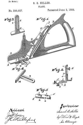
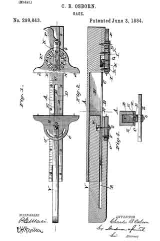
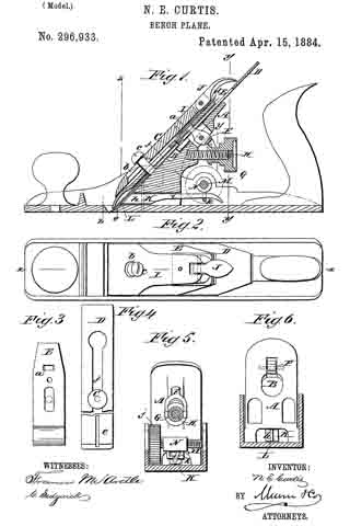
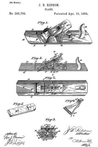
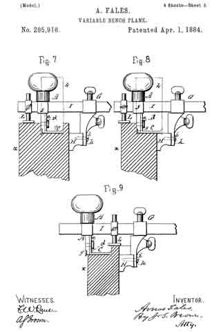
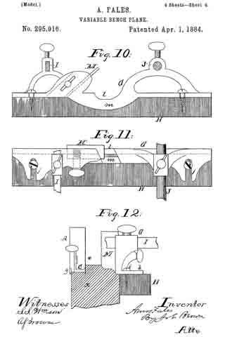
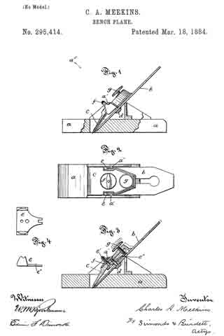
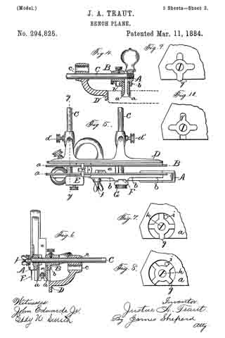
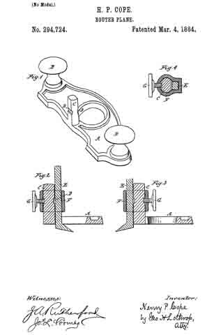
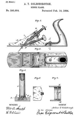
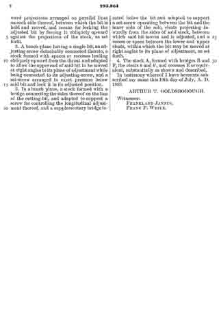
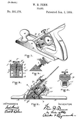
Figure 1 is a view in longitudinal central section of my improved plane. Fig. 2 is a top view of the same. Fig. 3 is a side view of the same. Fig. 4 is a view in cross-section of the adjustable yoke on plane denoted by line x x of Fig. 3. Fig. 5 is a detail perspective view of the carriage which supports the plane-iron.

Our invention relates to the class of planes having a flexible face and means for adjusting the plane-face for working on a convex or concave surface.

It also embraces certain features of construction applicable broadly to planes.

lt consists in the combination of a plane-body with a flexible face and means for adjusting the face, and in the combination of devices for holding and adjustiiig the cutting-iron of the plane-body, as more particularly hereinafter described.

In the accompanying drawings, the letter a denotes the plane~body as a whole,made of any suitable material — as iron — having a bed, a’, through which the plane-iron projects, vertical sides a5, which support the face and the blade-adjusting devices, respectively. The flexible face b is fast to the plane-base, and the forked arms c and d are pivoted to the plane-body, as by means of pivots c’ d’, and to the outer ends of the face, as by means of the links c and f. Each of these levers has a short arm, c2 d2, pivotally connected to each other by rods g, The yoke h is pivoted at its lower end to each arm of the lever c near the pivots c’, and bears between the upper and lower crossbars, h1 h2 , an adjusting-screw, i, which is arranged about centrally of the plane-body in a threaded socket in the cross-piece a2, fast to the plane-body in front of the plane-iron. Any vertical movement of the yoke imparted to it by the adjusting-screw i is transmitted to the lever c, and by means of connecting-rods g to the lever d, and from these levers c d to the opposite extremities of the flexible plane-face. This adjustment of the plane-face may be made to a convex surface, as denoted by dotted lines in Fig. 1, or to a concave with equal ease.

The adjustable carriage k is supported in the plane-body by means of the longitudinal and central bearings, l l’, the former resting upon the cross-bar a2, fast to the plane-body, and the latter in a tubular socket, a1, in the plane-body. The carriage k has the downward-projecting lugs k1 k2, against the inner faces of which bear the opposite ends of an adjusting-screw, m, which moves in a threaded socket in the cross-bar a3, fast to the plane-body. This carriage also has the arms n, with the inward-projecting extremities n’, so arranged as to grasp the upper surface of the clamp-iron o, placed over the iron p upon the carriage, when the parts are in position in the plane-body. The lower end of the clamp-iron bears upon the plane-iron just back of the cutting-edge, and its upper end bears the clamp-screw o’, moving in a threaded socket near the upper end of the clamp, and with its point bears upon the upper surface of the plane-iron. The central bearings of the carriage permit of a lateral motion of the carriage and the supported plane-iron, by means of which the plane-iron may be adjusted to a perfect bearing in the socket in the body. The peculiar method of holding the adjusting-screw between the lugs projecting from the carriage prevents backlash or lost motion of the parts and permits a more careful adjustment.

The plane-body, yoke, and the carriage of our improved plane are made, preferably, of metal — as iron — cast to shape, with threaded sockets and bearings for the adjusting-screws and bearings for the carriage formed in subsequent operations.

The main advantage of our improved device is the low cost of its manufacture and simplicity of the operating parts, which perform the functions attainable in like devices of the prior art only at considerable expense.

The peculiar method of holding the clamping-screw between the lugs on the lower part of the carriage relieves the maker of the tool from exercising any great care to get the bearings for the carriage and the axis for the adjusting-screw parallel, as the opposite ends of the adjusting-screw may have lateral play between the lugs and not render the device inoperative.

The plane may be quickly changed from a single-iron plane to a double-iron plane by sliding back the clamp, and the plane-iron adjusted for cutting without changing the clamp, but by simply turning the adjusting-screw m.

We claim as our invention —

1. In combination, in a flexible face-plane, a plane-body, a, a flexible face, b, levers c d, pivotally connected to the plane-body, to each other by connecting-rod g, and to the flexible face-plate, with means for changing the position of said levers and of the flexible face, all substantially as described.

2. The combination of a plane-body, flexible face, pivoted levers connecting the said face and the body, a yoke, h, pivotally connected to the said levers, and an adjusting-screw, i, having bearings in the yoke and in the plane-body, all substantially as described, and for the purpose set forth.

3. The combination of a plane-body, a, a carriage, k, with the central bearings, l l’, fitted to suitable bearings in the plane-body, and with lugs k1 k2, bearing upon opposite extremities of an adjusting-screw, m, attached to the body, all substantially as described.

4. In a plane, the combination of a plane-body, a, a carriage, k, with central bearings, l l’, projecting lugs k1 k2, and projections w’, an adjusting-screw, m, with its opposite ends bearing on the inner faces of the lugs, plane-iron p, and clamp-iron o, with clamp-screw o’, all substantially as described.

5. In a plane, the combination of a plane-body and a carriage having lugs bearing upon opposite extremities of an adjusting-screw, m, movable in a socket in a plane-body, all substantially as described, and for the purpose set forth.

6. In combination, a plane-body, a, having bed a’, cross-bars a2 a3, and socket a4, the forked levers c d, pivoted to the body, connecting-rods g, yoke h, pivoted to the levers, and adjusting-screw i, with plane-iron p and means for holding the same in the body, all substantially as described, and for the purpose set forth.

SOLON R. RUST.
ARTHUR E. RUST.

Witnesses:
JOSEPH W. DREYRUON,
O. S. THOMPSON.

No. 300,266 – Cabinet-Shave (John A. Keiser) (1884)

[paiddownloads id=”367″]300266


UNITED STATES PATENT OFFICE.

_________________

JOHN A. KEISER, OF CINCINNATI, OHIO, ASSIGNOR TO SAMUEL C. TATUM & CO., OF SAME PLACE.

CABINET-SHAVE.

_________________

SPECIFICATION forming part of Letters Patent No. 300,266, dated June 10, 1884.
Application filed February 28, 1884. (No model.)

_________________

To all whom it may concern:

Be it known that I, JOHN A. KEISER, a citizen of the United States, and a resident of Cincinnati, in the county of Hamilton and State of Ohio, have invented certain new and useful lmprovements in Cabinet-Shaves, of which the following is a specification.

My invention relates to an improved cabinet-shave, and other similar tools.

The object of my invention is to provide ready means for removing or inserting the bit or knife, all of which will be fully set forth in the description of the accompanying drawings.

Figure 1 is a perspective view of my invention with the bit removed. Fig. 2 is a front elevation of my improvement with the bit in position for use. Fig. 3 is a bottom plan view of Fig. 2. Fig. 4: is a vertical section on line x x, Fig. 2.

A A represent the handles of my improved shave.

B represents the central portion of the stock of the shave, which, with the handles, is preferably made of malleable iron, cast in one piece. a represents ears cast on and with the stock B.

C represents the swiveling or detachable bit-face; C’, the stationary bit-face, which forms a part of the stock B.

b represents ears attached to the face C, and provided with pivots i, which hinge the ears b to the ears a.

d represents a yoke or bar connected to the ears b.

The parts C, b, b, and d are made of metal formed in one piece, and arranged so as to more freely upon the pivots i.

D represents a cam connected by pivot c to the center of the yoke d.

E represents the bit or knife, which is made to fit into the head B, as shown in Figs. 2 and 4. In order to hold the knife in position by detachable fastenings, it is essential to have it gripped at two points — first, at or near the cutting edge, and, second, at the central point of the knife, sufficiently near the upper end to prevent its rocking or moving. To accomplish this I provide lugs h, at each end of the cutter E on the bottom of face C, and adapted to bear against the cutter E upon each side of the shaving-slot L.

The mode of operation in inserting the knife is as follows: Fig. 1 represents the device with knife or bit removed from the stock of the shave and the cam D hanging loosely upon the yoke d. The knife E is inserted with the proper feed, (the edge depending below the faces C C’,) and cam D is turned upward so as to bring the shoulder against the face ofthe knife. This movement draws the lugs h, on the face C firmly against the blade E, pressing or gripping it tightly against the face C’ of the stock by the inward movement of the face C, caused by the pressure of the shoulder of cam D against the upper end of the knife, forcing the yoke d outward. This mode of constructing the stock and attaching the parts holds the knife firmly in position, and yet allows it to be instantly inserted and removed.

The principal feature of my invention consists in constructing the pivoted portion of the stock so as to grip the knife near the cutting-edge, and central at or near its upper end, and at the same time not be apt to become accidentally disconnected from its bearings.

An inferior modification of my invention would be to employ a thumb-screw passing through the yoke d, instead of the cam D, for gripping the upper end of the knife E. Such a construction would be covered by the first and second claims herein. Spokeshaves and other tools could be made in a similar manner as the within-described cabinet-shave. Another modification could be made by having the lugs h, attached to the face C’ and the shaving-slot in the same side of the bit-face. So, too, one lug h might be employed near the center of the bit-plane; but it would not be as efficient as the plan here shown.

I claim —

1. A shave composed of the stock B and bit-face C’, in combination with the bit-face C, swiveled by a pintle placed parallel with the axis of rotation of the bit-face, and a fastening device, D, suitably supported, and adapted to grip the bit at or near the top and force one of the bit-faces against the lower edge of the bit, whereby the bit will be held to its place by said fastening D and bit-face, independently of other fastenings, substantially as described.

2. The combination, with the stock B and stationary bit-face C’, of the bit-face C, provided with lugs h to bear against the bit and with yoke d, and swiveled by a pintle parallel with its axis of rotation, and a fastening device, D, connected with the yoke d and adapted to bear against the upper part of the bit, the bit being held to its place by said fastening D and the face C, independently of other fastenings, substantially as described.

3. The combination of the stock B and stationary bit-face C’, provided with ears a, the bit-face C, provided with ears b and yoke d, and swiveled to ears a by pintles i, and the cam-lever D, fulcrumed on yoke d, for instantaneonsly fastening and releasing the bit, substantially as described.

In testimony whereof I have hereunto set my hand.

JOHN A. KEISER.

Witnesses:
EDWARD BOYD,
ANDREW E. SCOTT.

No. 299,927 – Plane (Samuel E. Hilles) (1884)

[paiddownloads id=”366″]299927


UNITED STATES PATENT OFFICE.

_________________

SAMUEL E. HILLES, OF CINCINNATI, OHIO.

PLANE.

_________________

SPECIFICATION forming part of Letters Patent No. 299,927, dated June 3, 1884.
Application filed March 19, 1884. (No model.)

_________________

To all whom it may concern:

Be it known that I, SAMUEL E. HILLES, a citizen of the United States, and a resident of Cincinnati, in the county of Hamilton and State of Ohio, have invented certain new and useful Improvements in Planes, of which the following is a specification.

My invention relates to an improvement in planes.

The object of my invention is, first, to provide suitable attachments for holding the cutter or bit in position; second, to provide improved means for attaching both vertical and side guides to regulate the cutting of grooves, gains, or rabbets.

The invention consists in the novel construction and combination of devices hereinafter described and claimed, reference being had to the accompanying drawings, in which —

Figure 1 is a perspective view of my invention, with the attachments in position for use. Fig. 2 is a central vertical section on line x x, Fig. 1. Fig. 3 is a detail view of the vertical guide; Fig. 4, a perspective view of the side guide; Fig. 5, a detail view of one of the attachments of the side guide.

A B represent an L-shaped plane-stock; C, a handle, the parts being preferably cast in one piece.

a represents a flange upon which the cutter b rests. It is desirable in a plane to provide means for quickly and easily securing the cutter in position, and which can be readily inserted or removed, dispensing with the set-screw, and using instead thereof a cam or eccentric, which bears upon the wide face of the bit or cutter, and holds it more firmly in position than a set-screw, and which can be also more readily set or detached, being more durable than when the cap is secured by screw-threads, which must be formed in the plane-stock, or in the cap, so that common grey iron cannot be practically employed for that purpose.

E represents my improved cap, provided with a lug, e, extending transversely across its upper face, and which engages with the groove formed in the under face of boss D, said groove and lug being arranged across or substantially at right angles to the line of travel of the tool, so that the cap is thereby prevented from longitudinal movement. This lug e and the groove in the face of boss D are rounded or V-shaped, so as to prevent the cap E from being driven downward as the cam-lever F is turned down. A rectangular gain and lug would cause the parts to bind, and not allow the cap E to be raised vertically if the parts are fitted so as to prevent longitudinal motion. The cap E is inserted and removed laterally.

F represents a cam-lever fulcrumed upon the cap E, the face of the cam being as wide as the cutter b, and which when turned down upon the cutter, as shown in Fig. 1, securely holds it in its position on the bed or flange a. The cutter can be loosened, and it, with the cap, quickly removed by turning up the cam F.

G represents a gage or fence, which is secured to the side plate, B, in the following manner:

c represents a vertical groove cut in the face of the side B.

d represents a lug cast on the inner face of the guide G, which engages with the groove c and prevents lateral movement of the guide.

h, represents a slot, pierced through the shank of guide G, through which passes the shank of set-screw H, which taps into the side stock B of the plane, and holds the gage in position. This construction allows the gage G to be adjusted up and down, and secures its adjustment upon the side of stock B without weakening the stock, and in this respect it is an improvement upon the device shown and described in Letters Patent No. 284,941, granted J. M. Bennett, September 11, 1883. The guide G maybe readily removed when it is desired to use the plane with the side B resting against the wood, as in planing into a corner. It is also desirable to provide a side gage, which may be readily attached to or removed from its position on the stock of the plane, and which can be secured thereto in such a manner as not to weaken the stock, which is preferably made of common grey iron. For this purpose I provide a boss, I, on the top face of stock A.

J represents a gage-stock, which is provided with a gain, K, on one of its edges, which gain is of the same width as the side gage, M, so as to allow it to be retracted outward a sufficient distance to employ the full width of the cutter b.

l represents lugs formed upon one side of the gage-stock J, which rests upon the top surface of the stock A, and prevents it from rocking.

L represents a thumb-screw, which is inserted through the gage-stock J, and taps into the boss I, rigidly securing stock J in position to firmly hold the gage M.

n represents a transverse gain cut upon the under surface of the gage-stock J. It is made of the proper shape to receive the slotted shank N, which slides laterally in the gain n, for adjusting the gage M to any desired width of cut.

O represents a set-screw for attaching the gage M to the gage-stock J in such a manner as to adjust the gage, as before described. It will be seen that the gage-stock J and the gage M can be readily attached to or removed from the plane-stock by means of the attaching screw L.

I claim —

1. The combination, in a plane, of the right-angled stock A B, having the flange a, and attached lateral boss D, constructed with a longitudinal groove on its under side, the cap E, having a lug, e, extending transversely across its upper face, and adapted to be slipped sidewise into engagement with the groove of the boss to prevent movement of the cap in the direction of its length, and the swinging cam F, pivoted to the upper end of the cap, for clamping the cutter b upon the flange a substantiallty as described.

2. The combination, with the plane-stock A B, formed with a groove, c, in one side of the part B, but not extending through it, of the adjustable gage G, slotted vertically and provided with the lug d and the set-screw H passed through the slot of the gage and tapped into the part B of the stock, substantially as described.

3. The combination, With the right-angled stock A B, having the boss I on the top face of the part A, of the gage-stock J, provided with lugs l, resting on the face of stock A, and the thumb-nut L inserted through the stock J, and tapped into the boss I to secure stock J in position, substantially as described.

4. The combination of the right-angled stock A B, provided with the boss I on the face of the part A, the gage-stock J, provided with lugs l resting on the face of stock A and , formed with the transverse gain n, and secured to the stock by screw L, the gage M, formed with slotted shank N, entering gain n, and screw O for attaching gage M to stock J substantially as described.

In testimony whereof I have hereunto set my hand.

SAML. E. HILLES.

Witnesses:
ANDREW E. SCOTT,
A. GLUCHOWSKY.

No. 299,843 – Gage (Charles B. Osborn) (1884)

[paiddownloads id=”365″]299843


UNITED STATES PATENT OFFICE.

_________________

CHARLES B. OSBORN, OF CANANDAIGUA, NEW YORK.

GAGE.

_________________

SPECIFICATION forming part of Letters Patent No. 299,843, dated June 3, 1884.
Application filed April 12, 1884. (Model.)

_________________

To all whom it may concern:

Be it known that I, CHARLES B. OSBORN, a citizen of the United States, residing at Canandaigua, in the county of Ontario and State of New York, have invented certain new and useful Improvements in Dado-Guides for Planes; and I do declare the following to be a full, clear, and exact description of the invention, such as will enable others skilled in the art to which it appertains to make and use the same, reference being had to the accompanying drawings, and to letters or figures of reference marked thereon, which form a part of this specifiction.

Figure 1 of the drawings is a face view of my device. Fig. 2 is a vertical sectional view of the same, and Fig. 3 is a transverse section.

This invention has relation to adjustable guides for dado-planes; and it consists in the construction and novel arrangement of the longitudinally-recessed rule, carrying a slotted guide-plate and cam, the slotted extension-bar engaging the guide-plate, a second radially-adjustable clamp-jaw, pivoted to said extension-bar, and devices for holding the extension-bar and clamp-jaws in position after adjustment, substantially as specified.

In the accompanying drawings, the letter A designates the rule or guide-bar, against which the dado-plane is designed to work. In the bottom of this bar is made a longitudinal recess, B, and it is provided with an under face-plate, C, which is longitudinally slotted at D, below the recess of the bar. The lateral margins of the slot D project inwardly beyond the walls of the recess, to forrn slide-guides E for the extension.

F indicates the rear clamp-jaw, which is connected to the rule near its end by a clamp-screw and a pivot, G, which engages a spring, H, in a recess of the rule, giving a little play to the clamp-bar in the direction of the length of said rule. The clamp-screws K pass through a strap, L, and through slots I, which are extended radially in series around the center of the jaw. When the clamp-screws are loosened, the jaw can he turned to the required angle, and then by turning the clamp-screws it can be held at that angle firmly. The biting or holding edge N of the jaw, which is to be pressed against the work, is preferably provided with small teeth a. The slots through which the clamp-screws pass are diametrically opposite to each other, and allow the clamp-jaw to be pressed back a little by the spring. In rear of the clamp-jaw is pivoted a cam, P, which engages the circular back b of the clamp-jaw. When this cam is turned in the proper direction, it will force the jaw forward against the work. The slide bar or extension V is slotted in its sides, or entirely through from side to side, as indicated at R, to engage the guide-edges E of the slotted plate C. This extension is designed to fill the recess of the rule-bar neatly, but so that it will slide easily in its bearing.

Z represents the clamp-jaw, which is pivoted to the inner end of the extension by the clamp-screw S, which engages a nut, T, under the slotted guide-plate C. When the clamp-screw S is turned up hard, it secures the extension-bar in the position to which it has been adjusted with relation to the rule-bar. The clarnp-jaw Z is usually provided with small teeth, and is slotted, as at c, to receive a clamp-screw, J, whereby said jaw is held firnily in position after its angular adjustment.

In operating this device the clamp-screw S is loosened, and the jaws are adjusted to the proper angle for the work, which is received between them. The extension-bar and its jaw are then fastened up to the work, allowing about a quarter of an inch between the edge of the jaw and the work. Then the clamp-screw S is tightened and the cam P is turned forcibly, acting to press the jaws against the work. The rule is now fixed in position to guide the dado.

Having described this invention, what I claim, and desire to secure by Letters Patent, is —

A dado-guide consisting of the longitudinally-recessed rule, carrying a slotted guide-plate, a radially-adjustable clamp-jaw, and cam, the slotted extension-bar engaging the guide-plate, a second radially-adjustable clamp-jaw pivoted to said extension-bar, and devices for holding the extension-bar and clamp-jaws in position after adjustrnent, substantially as specified.

In testimony whereof I affix my signature in presence of two witnesses.

CHARLES B. OSBORN.

Witnesses:
G. GRANGER BENHAM,
BRADLEY WYNKOOP.

No. 296,933 – Bench-Plane (Norman Edward Curtis) (1884)

[paiddownloads id=”364″]296933


UNITED STATES PATENT OFFICE.

_________________

NORMAN EDWARD CURTIS, OF MAUSTON, WISCONSIN.

BENCH-PLANE.

_________________

SPECIFICATION forming part of Letters Patent No. 296,933, dated April 15, 1884.
Application filed January 28, 1884. (Model.)

_________________

To all whom it may concern:

Be it known that I, NORMAN EDWARD CURTIS, of Mauston, in the county of Juneau and State of Wisconsin, have invented a new and Improved Bench-Plane, of which the following is a full, clear, and exact description.

In the class of bench-planes having adjustable plane-irons it is common to adjust the plane-iron longitudinally by means of an adjusting screw and lever, and to clamp the plane-iron and its cap by means of a clamping-lever provided with a cam.

My invention provides means for the accurate and quick lateral adjustment of the plane-iron, and it consists in a fulcrum upon which the plane-iron may swing laterally, a longitudinal groove formed in the rear face of the iron, and a lever fulcrumed in the lower part of the plane, with its shorter arm entering the groove in the back of the plane-iron, and its longer arm extending rearward, to be operated by hand or by an adjusting-screw.

Reference is to be had to the accompanying drawings, forming a part of this specification, in which similar letters of reference indicate corresponding parts in all the figures.

Figure 1 is a vertical longitudinal section of my improved plane, taken on the line x x in Fig. 2. Fig. 2 is a plan view. Fig. 3 is a detail view of the cap-iron. Fig. 4 is a rear view of the plane-iron. Fig. 5 is a vertical transverse section taken on the line y y y in Fig. 1. Fig. 6 is a vertical transverse section taken on the line z z in Fig. 1, the irons being removed.

The body of the plane is of the usual form, having the bed-piece A attached thereto in the usual way. In the upper surface of the bed-piece A is formed a groove, B, of sufficient width and depth to receive the screw C, which clamps the plane-iron D and cap-iron E together. The groove B is of sufficient length to permit the greatest required range of longitudinal rnovement of the plane-iron, while it embraces the sides of the screw-head so closely as to admit of little or no lateral motion of the plane-iron at that point. The shorter arm of a lever, F, fulcrumed in the bed-piece A, extends into an aperture, a, in the cap-iron E. The longer arm of the lever F is engaged by a milled nut, G, on the screw-threaded stud H, projecting from the back of the bed-piece A. By turning the milled nut G the plane-iron D is adjusted longitudinally in the usual way. The plane-iron D and cap-iron E are clamped in place by a clamping-lever, I, having a slot bolt hole, b, near its lower end for receiving the screw c, which also passes through the plane-iron and the cap-iron. A cam-lever, J, pivoted in the upper end of the clamping-lever, presses on a bearing plate, d, carried by the lever I, and which, in turn, presses upon the upper end of the cap-iron. The lever I is similar to others in use; but lf have shortened the distance between the screw c and the lower end thereof, and have increased the distance between the said screw and the cam-lever J, so as to secure an increased leverage and a corresponding increase in the firmness with which the plane-iron is held in place.

In the back of the plane-iron D and from the lower end thereof along the middle a groove, e, extends toward the usual longitudinal slot, f, of the plane-iron.

In a mortise formed in the lower portion of the bed-piece A a lever, K, is fulcrumed, so as to swing in a plane parallel with the face of the plane-body. The shoulder-arm h of the lever K is beveled and provided with a tongue, L, entering the groove e in the back of the plane-iron D. The longer arm i of the lever K, extends beyond the rear of the bed-piece A, where it may be moved by the hand alone or by any suitable mechanical device. I prefer to employ a screw, M, journaled transversely in the plane-body, and having a milled head, j, and carrying a traveling nut, N, having a loop, k, for receiving the longer arm i of the lever K. By turning the screw M in one direction or the other the lever K is correspondingly moved, and the plane-iron, by virtue of its engagement with the lever, is swung laterally, the clamping-screw C being the center of motion. This adjustment enables the user to readily and accurately adjust the cutting-edge of the plane-iron to parallelism with the face of the plane; and, furthermore, the tongue L at the end of the lever K forms a guide which permits of replacing the plane-iron in the plane-body without the necessity of special adjustment each time it is removed and replaced. Where a single iron is used, a screw corresponding to the clamping-screw C will be inserted in the back thereof to form a pivot on which the iron may swing.

I have described one term of my invention. It is obvious that it adrnits of various modifications, such as substituting a rib for the groove in the back of the iron and making a groove for its reception in the end of the adjusting-lever. The adjusting-lever may be bifurcated and made to embrace the edges of the plane-iron when neither the groove nor the rib would be required. It will also be seen that the adjusting-screw may be arranged to act directly on the plane-iron to secure the necessary lateral movement. In view of these various possible modifications of my improvement, I do not limit or confine my invention to the precise form herein shown and described.

Having described my invention, I claim as new and desire to secure by Letters Patent —

1. In a bench-plane, the combination, with the pivoted plane-iron having in its lower rear side a longitudinal groove of the laterally-adjustable lever adapted to fit into the groove of the plane iron, and capable of adjustment by the hand, substantially as and for the purpose set forth.

2. In a bench-plane, the combination, with the longitudinally-grooved bed-piece, of the cap-iron having the rear headed projection or screw, with its head entering the groove of said bed-piece, and the adjusting-lever engaging said iron, and actuated by an adjusting-nut, substantially as and for the purpose set forth.

3. In a bench-plane, the combination, with the pivoted plane-iron having in its lower rear surface a longitudinal groove, of the laterally-adjustable lever having a tongue entering the groove of the plane-iron, and the headed screw carrying a nut or sleeve provided with a loop which receives the outer end of the aforesaid lever, substantially as and for the purpose set forth.

NORMAN EDWARD CURTIS.

Witnesses:
JOHN F. CURTIS,
GEORGE CURTIS.

No. 296,785 – Plane (Joseph B. Ripsom) (1884)

[paiddownloads id=”363″]296785


UNITED STATES PATENT OFFICE.

_________________

JOSEPH B. RIPSOM, OF OSHKOSH, WISCONSIN.

PLANE.

_________________

SPECIFICATION forming part of Letters Patent No. 296,785, dated April 15, 1884.
Application filed July 21, 1884. (No model.)

_________________

To all whom it may concern:

Be it known that I, JOSEPH B. RIPSOM, a citizen of the United States, residing at Oshkosh, in the county of Winnebago and State of Wisconsin, have invented a new and useful Plane, of which the following is a specification, reference being had to the accompanying drawings.

This invention relates to carpenters’ planes, and is especially adapted for use as a carriage-maker’s miter-plane. Its object is to provide a plane possessing superior advantages in point of simplicity, inexpensiveness, durability, and general efficiency.

In the drawings, Figure 1 is a perspective view of my improved plane. Fig-2 is a vertical longitudinal sectional view of the same. Fig. 3 is a vertical transverse sectional view taken on the line x x, Fig. 2. Fig. 4 is a top view of the plane with the bit, cap-plate, and eccentric lever removed. Fig. 5 is a detail perspective view of the bit. Fig. 6 is a detail perspective view of the cap-plate.

Referring to the drawings, A designates the stock, which is formed of metal and provided with the usual handle, B. This stock comprises a bottom plate, C, at the side edges of which are provided longitudinal flanges D D, that incline outwardly and upwardly from plate C at an angle, preferably, of forty-five degrees. The throat or slot E extends entirely across the plate C, so that the bit or cutter extends to the vertex of the angles formed by plate C and flanges D D. A transverse brace-plate, F, is preferably formed between the flanges D D and just in front of the throat E, while a transverse rib, G, is provided some distance in rear of the throat, and is formed with a screw-threaded recess, H. Between this rib G and the throat E are provided upright side danges I I, having perforations J, in which a cross-pin, K, is secured.

L is a lever-block, which is provided with an elongated perforation, M, at its front end, through which passes a fulcrurn-screw, N, into the recess H, and has also upright side flanges, O O, at this end, formed with perforations P. At the rear end of this lever-block is formed a screw- threaded perforation, Q, through which works a set-screw, R, against the bottom plate, C, to raise and lower the said lever, by which operation the bit can be set at different angles for convenience in cutting with or across the grain of the wood.

S is a bed-plate, which is provided with a longitudinal slot, T, having longitudinal side shoulders, U U, and also has downwardly-extending side flanges V V, formed with perforations W, through which a cross-pin, X, is passed to pivot the bed-plate to the lever-block. The bed-plate extends down between the flanges I I, and a set-screw, Y, works through the slot T, with its head against the shoulders U U, into a block or nut, Z, bearing against the under side of the bed-plate. The head of this set-screw engages a cross-slot, A2, in the bit or cutter B2, to retain the latter in position, and the screw is only to be moved as the cutter wears away.

C2 is a cap-plate, which is preferably formed of steel, and is bowed to form a spring, as shown. This plate is preferably formed with end shoulders, D2 D2, which engage corresponding shoulders, E2 E2 at each side the throat E.

F2 is an eccentric lever, comprising an operating-handle, G2, and an eccentric head, H2, formed with a transverse groove, l2, by which it can be engaged under the pin K, to bind against the spring-plate and secure the bit in position against the bed-plate.

The operation and advantages of my invention will be readily understood and appreciated. It is very sirnple and efiicient in construction, and its parts can be easily governed and adjusted. By turning the set-screw R the bit will be given cut, and when the screw is turned back the tension of the spring cap-plate will automatically return the bit to its former position.

I claim as my invention —

1. The combination, with the stock comprising the bottom plate having the longitudinal side flanges inclined outwardly and upwardly at an angle from the bottom plate, and formed with the throat extending entirely across the bottom plate to the vertex of the angle formed by the bottom plate and side danges, of a lever-block fulcrumed on the stock, a set-screw for operating the said lever, a bed-plate connected with the lever, the bit carried by the bed-plate, and means for securing the bit in position, substantially as set forth.

2. The combination of the stock having the throat and upright flanges, the cross-pin between the latter, the lever-block having the fulcrum-perforation, and disposed just above the bottom plate and in rear of the throat, the fulcrum-screw, the set-screw for adjusting the lever, the longitudinally-slotted bed-plate pivoted on the lever, the set-screw working in the slot in the bed-plate, the bit having the slot for receiving the head of this screw, the spring cap-plate, and the eccentric lever under said cross-pin and acting to clamp down the spring cap-plate, substantially as and for the purpose set forth.

3. The combination, in a plane, of the main bottom lever, the set-screw working through the free end of the lever, a bed-plate pivoted to the lever at its fulcrurn end, the bit or cutter connected with the bed-plate, the bowed spring cap-plate, the cross-pin K, and the eccentric lever adjustable under this pin and against the springplate, whereby the bit can be adjusted by the set-screw and will be returned by the said spring-plate, substantially as set forth.

4. The combination of the bed-plate having the longitudinally-disposed slot formed with longitudinal side shoulders, the set-screw working through the slot with its head against the shoulders, the nut receiving the screw and bearing against the under side of the bed-plate, and the bit having the transverse slot that received the head of the set-screw, the bit being carried and adapted to be fed by adjusting said screw, substantially as set forth.

5. The combination of a bed-plate, the bit or cutter connected thereto, the bowed spring cap-plate, the cross-pin K, and the eccentric lever having the eccentric head formed with the transverse slot, substantially as and for the purpose set forth.

In testimony that I claim the foregoing as my own I have hereto aftixed my signature in presence of two witnesses.

JOSEPH B. RIPSOM.

Witnesses:
JOHN BAUMGARTNER,
GUSTAV EILERS.

No. 296,207 – Joiner’s Plane (George D. Mosher And William H. Ford) (1884)

[paiddownloads id=”362″]296207


UNITED STATES PATENT OFFICE.

_________________

GEORGE D. MOSHER AND WILLIAM H. FORD, OF BIRMINGHAM, CONN.

JOINER’S PLANE.

_________________

SPECIFICATION forming part of Letters Patent No. 296,207, dated April 1, 1884.
Application filed January 21, 1884. (No model.)

_________________

To all whom it may concern:

Be it known that we, GEORGE D. MOSHER and WILLIAM H. FORD, of Birmingham, in the county of New Haven and State of Connecticut, have invented a new Improvement in Joiners’ Planes; and ive do hereby declare the followiing, when taken in connection with accompanying drawings and the letters of reference marked thereon, to be a full, clear, and exact description of the same, and which said drawings constitute part of this specification, and represent, in —

Figure 1, a left-hand side view; Fig. 2, a right-hand side view, Fig. 3, a face view; Fig. 4, a sectional side view, to illustrate the adjustment of the cutter, Fig. 5, a section on line x x, looking downward, to show the connection between the cutter and the hub of the adjusting-lever.

This invention relates to an improvement in planes for joiners’ use, particularly to that class in which the stock is constructed from cast metal.

The principal object of the invention is to construct the stock with the mouth and throat extending entirely across it, and whereby the possibility of “choking” is avoided; but it also has for its object a simple and easy adjustment of the cutter; and the invention consists in the construction, as hereinafter fully described, and more particularly recited in the claims.

A represents the rear portion, and B the front-portion, between which the mouth a is formed. This mouth extends entirely across the face of the plane, as seen in Fig. 3, instead of leaving a connection between the front and rear portions at each end of the mouth, as in the usual construction. As the front and rear parts of the stock are separated by this mouth, We connect them above and over the throat C by a connection, D, extending from the handle E at the rear to a handle, F, at the front. This connection is made in the form of a thin web centrally on the stock, so as to make the plane as light as it conveniently can be. The back of the throat is inclined to form a seat, b, for the cutter d in the usual relation to the mouth. From the seat b a standing screw-threaded stud, e, extends forward at right angles to the seat, over which the cutter will set, the cutter being constructed with a slot for such purpose, and so as to permit the cutter to be moved up or down, as occasion may require. The cutter placed thereon, a cap or clamping piece, f, is applied over the bolt, and then a nut, h, turned thereon, clamps the cutter to its seat. This stud e is best fixed in place by being introduced into the mold and the metal cast around it.

As a simple and convenient means for adjusting the cutter, we arrange a lever, i, upon a hub, l, which extends through the web, and so as to take a seat therein and permit the hub to be turned by applying the fingers to the lever. The handle stands upon one side of the web, as seen in Fig. 5.

On the cutter, above the stud e, is a stud, m. From this stud a link, o, extends up to the hub l on the opposite side to the lever i, and is there connected to the hub by an eccentric pin or screw, p, as seen in Fig. 5. Therefore by turning the lever i the eccentric pin p imparts a corresponding movement to the link, and thence to the cutter, so that turning in one direction the cutter may be drawn upward, or in the opposite direction forced downward, according to the adjustment required.

By this construction of plane the throat and mouth are open from side to side, so that the cuttings or shavings must readily pass out of the throat, and cannot by any possibility be stopped therein, so as to choke the mouth. The adjustment of the cutter is simple and cheap.

We are aware that metal planes have been constructed with the mouth extending from side to side in like manner as in what are known as “rabbet-planes,” and therefore do not claim, broadly, such a plane.

We claim —

1. A cast-metal plane having the front and rear portions separated by the mouth and throat, whereby said mouth and throat are open from side to side, the front and rear portions connected over the throat, the rear portion constructed vvith a seat, b, for the cutter, said seat provided with a fixed screw-threaded stud, e, the cutter d, the clamp f, and nut h, substantially as described.

2. A cast-metal plane having the throat and mouth open from side to side, the rear and front portions of the stock connected centrally centric connection with the hub of said lever, over the throat above the cutter, the rear portion constructed with a, seat to receive and support the cutter, the adjusting-lever i, arranged above the cutter in the connection which unites the rear and front portions, and a link in connection with the cutter and in eccentric connection with the hub of said lever, substantially as described.

GEORGE D. MOSHER.
WILLIAM H. FORD.

Witnesses:
EDWIN B. GAGER,
ANDREW J. EWEN.

No. 295,916 – Variable Bench-Plane (Amos Fales) (1884)

[paiddownloads id=”361″]295916


UNITED STATES PATENT OFFICE.

_________________

AMOS FALES, OF DENVER, COLORADO.

VARIABLE BENCH-PLANE.

_________________

SPECIFICATION forming part of Letters Patent No. 295,916, dated April 1, 1884.
Application filed March 31, 1883. (Model.)

_________________

To all whom it may concern:

Be it known that I, AMOS FALES, of Denver, in the county of Arapahoe and State of Colorado, have invented certain Improvements in Variable Bench-Planes; and I do hereby declare that the following is a full and exact description thereof, reference being had to the accompanying drawings, making part of this specification.

These improvements are upon variable bench-planes constructed upon the general plan set forth in Letters Patent granted to me March 7, 1882, No. 254,542, and are mainly additional thereto, although I have in one or two respects changed and improved the construction therein shown and described. Except as to these changes, as hereinafter specified, I use the invention substantially as described in the said Letters Patent; but it is to be understood that the improvements herein described and claimed may be applicable to other constructions of bench-planes besides those therein set forth; and my invention is intended to embrace all applications to which the several features, any or all, may be adapted.

In the accompanying drawings, Figure 1 represents a front side view of the main stock of the bench-plane and parts belonging thereto, constructed with my present improvements, Fig. 2, a front side view of the auxiliary stock and attached parts constructed with my present improvements 5 Fig. 3, a back side view of the said auxiliary stock; Fig. 4, a top view of the two stocks connected together for use; Fig. 5, a front view of the stocks arranged as in Fig. 4; Fig. 6, a front view of the two stocks arranged for tonguing; Fig. 7, a front view of the stocks arranged for grooving; Fig. 8, a similar view of the stocks arranged to constitute a front fillister; Fig. 9, a similar view of the stocks arranged for a back fillister; Figs. 10, 11, and 12, views showing the construction of the auxiliary stock adapted to other kinds of work.

Like letters designate corresponding parts in all the figures.

First, in the construction of the main stock A, I employ an improved handle, as represented in Figs. 1 and 4. The handle proper, B, is turned in simple cylindrical form, with one side slightly flattened to rest upon a straight plane-surfaced flange, a, cast upon the stock. Screws b b attach the handle to the flange, which is suitably inclined to give the handle the proper position for grasping. Not only is this construction of the handle very simple and cheap, but it is very easy for the hand and convenient for use in connection with other parts of the instrument, not interfering with the adjustment of the cutters; also, the molds or form-plates C D, instead of having shoulders to fit under the lower edge of the stock-flange c, for holding them in proper position, I now form their vertical attaching-flanges d d each with upward extensions e e, to bear against the shoulder formed by the projecting lower edge of the body f of the stock. This construction of the form-plates leaves the lower edge of the stock-flange c free and unobstructed and enables me to permanently attach thereto one dado-spur, g, as shown in Figs. 4 to 9 of the drawings, and saves the expense of two spurs on each dado. and it is always in position for use.

Another change in the construction of the main stock consists in terminating the lower part of the cutter-bracket E at the line of the shoulder or lower edge of the body f of the stock, thereby leaving the stock without side projections beyond the stock-flange below the said line, so that very narrow grooves may be out to the full depth of the said flange.

Second, in the construction of the auxiliary stock G, I form the stock and cutter-holder in one instead of two parts or sections, thus simplifying and cheapening the construction and rendering the use ofthe stock more convenient, and enabling me to apply any other attachment which may be desired. The stock thus approximates in construction and use to the main stock.

Further, for many purposes the fiange h of the auxiliary stock extends lower than or entirely below the corresponding flange, c, of the main stock, as shown in Fig. 5 and following figures of the drawings. This enables me to use, if desired, a cutter in the main stock, which may extend laterally over the auxiliary stock, as shown, for instance, in Fig. 5. Besides, it enables me to employ, in connection with the auxiliary stock, a “fence” or gage and guide-strip, H, for uses such as illustrated in Figs. 7, 8, and 9, and hereinafter set forth. This fence is preferably made of wood, and is consequently cheap and light. It is made of the form shown or any other most convenient. It is attached to the flange h of the auxiliary stock below the body thereof, which forms a guide-shoulder, by two screws, i i passing through notches j j of the stock-flange, so that it is easily attached and detached. Its surface, which faces the main stock, is plane and parallel therewith. By adjusting the auxiliary stock to the required distance from the main stock on the connecting-bars I J this fence may be brought to bear against and run along one side of the stuff to be worked, and serve as a guide for the instrument and gage for the work.

In Figs. 4 and 5 and the following figures of the drawings I illustrate the operation of the instrument provided with the above-de-
scribed improvements.

In Figs. 4 and 5 is shown an arrangement for a front fillister, with a wide cutter, k, in the main stock overlapping the auxiliary stock, which in this case needs no cutter, but is low enough in the middle to allow the lapping over of the main-stock cutter. The flange h furnishes the side gage, and the vertical gage-stop L is mounted on the connecting-bar I, back of the main stock, to gage the depth of the cut in the board or stuff x, indicated by dotted lines in Fig. 5.

In Fig. 6 is shown an arrangement for tonguing. Here also the flange h of the auxiliary stock serves as the side gage, and the vertical gage-stop is mounted between the two stocks. The cutter k of the main stock cuts behind the tongue of the board x, and a cutter, M, in the auxiliary stock cuts in front of the tongue.

In Fig. 7 I show an arrangement for grooving. In this arrangement a fence, H, is used on the auxiliary stock for the side gage, and the vertical gage-stop I is arranged back of the main stock, the cutter k of the main stock cutting the grooves in the board or plank x, in connection with the fixed dado-spur g on the main-stock flange.

In Fig. 8 is shown an arrangement for a front fillister, with the use of a fence, H, on the auxiliary stock. By this arrangement as narrow a rabbet or shoulder may be cut in the stuff as ever will be required.

In Fig. 9 is shown an arrangernent for a back fillister, a fence, H, on the auxiliary stock furnishing the side gage, and the vertical gage-stop L being mounted between the two stocks.

Figs. 10, 11, and 12 show a construction of the auxiliary stock adapted to kinds of work in which it is not convenient for the flange h to project lower than the main stock — as, for instance, in making window-sashes. Here the stock-flange h projects horizontally, and the fence H is attached below it, the attaching-screws i i going down through notches j j, which allow a lateral adjustment of the fence.

As seen in Fig. 12, the screws i i enter the fence nearer one edge than the other. When the fence is attached, as shown, the fence is back of the front side of the stock, allowing the cutter M of the stock to cut over the sash x or other article. By reversing the position of the fence, however, the edge of the same projects in front of the stock, as required for some kinds of work. There is a notch or depression, l, Figs. 10 and 11, in the middle of the auxiliary stock, to allow the center of the main stock to reach over the auxiliary stock, when desired. The auxiliary stock is depressed under this notch, the fence being cut away to allow the two to come together.

I claim as my invention —

1. In a bench-plane, a handle, B, made of cylindrical form, flattened on one side, in combination with an inclined plane-faced flange, a, on the plane-stock. substantially as and for the purpose herein specified.

2. The combination of the main stock A, having the lower edge of its body f and cutter-bracket E in one straight line, and its flange c provided with a dado-spur, g, and the form-plates C D, having vertical attaching-flanges d d bearing against the straight lower edge of the said stock-body and bracket, and adapted to have their lower surfaces flush with the lower edge of the said stock-flange, substantially as and for the purpose herein specified.

3. The reversible fence H, in combination with the stock G, the points of attachment being to one side of the middle longitudinal line of the fence, whereby two positions are given thereto fulfilling two purposes, substantially as herein specified.

4. The combination of the main stock A, having a downwardly-extended flange, c, on its lower edge, and a cutter extending laterally beyond the stock, and the auxiliary stock G, cut away at the top to allow the main-stock cutter to project over it, and having a flange, h, bent laterally, substantially as and for the purpose herein specified.

In testimony whereof I have signed my name in presence of two witnesses.

AMOS FALES.

Witnesses:
J. DEWEESE,
H. T. CASTLE.

No. 295,414 – Bench-Plane (Charles A. Meekins) (1884)

[paiddownloads id=”360″]295414


UNITED STATES PATENT OFFICE.

_________________

CHARLES A. MEEKINS, OF NEW HARTFORD, CONNECTICUT.

BENCH-PLANE.

_________________

SPECIFICATION forming part of Letters Patent No. 295,414, dated March 18, 1884.
Application filed May 31, 1883. (No model.)

_________________

To all whom it may concern:

Be it known that I, CHARLES A. MEEKINS, of New Hartford, in the county of Litchfield and State of Connecticut, have invented a certain new and useful Improvement in Bench-Planes, of which the following is a description, reference being had to the accompanying drawings, where —

Figure 1 is a side view, with a portion of the sides of the stock represented as broken away. Fig. 2 is a view looking diagonally down upon the top from the point a5 over Fig. 1. Fig. 3 is a view of the plane in central vertical lengthwise section. Fig. 4. shows a detail top view of the rocking clamp-iron, and also a detail side view of the same.

The letter a denotes the stock or body of the plane, which may he partly of wood and partly of metal, or substantially wholly of wood or wholly of metal. In the drawings I show it with the bottom part composed of wood and the upper part of iron.

The letter b denotes the chisel or plane-iron, of the ordinary kind. The letter c denotes the cap-iron, which is novel in its construction; but it is secured to the plane-iron b, in substantially the ordinary way, by the connecting-screw d.

The letter e denotes what I call the “rocking clamp-iron,” because it has a rocking motion for effecting the adjustment of the plane-iron and cap-iron on the studs or pivots a’ a’; and it also serves in a novel manner the function of a clamp-iron-that is, it is the important factor in attaching the plane-iron and the cap-iron to the stock of the plane. This rocking clamp-iron runs under the cap-iron. The pin e’, jointed somewhat loosely at the bottom to the rocking clamp-iron, projects upward through the cap-iron, and upon the upper end bears the nut f, by means of which the plane-iron and cap-iron are clamped to the stock — that is, by running the nut down, the journal ends of the rocking clamp-iron press against the studs a’ a’, and the plane-iron is forced firmly down upon its seat. This rocking clamp-iron has an extended part or lever end, e”, the end of which is bifurcated, and takes hold of an annular groove in the adjusting-screw g, which is hung in the cap-iron.

By manipulating this adjusting-screw the edge of the plane-iron may be nicely adjusted. The mode or manner in which this is effected is not, perhaps, plain at a first glance; but the explanation is that by manipulating this adjusting-sorew the clamp-iron is rocked on pivots a’, and carries the plane and cap irons with it in its up and down but not its rocking movements.

I claim as my improvement —

1. In combination, the plane-body bearing the pivots, the plane-iron, the cap-iron attached to the plane-iron, the longitudinally-rocking clamp-iron, adjustably connected to the cap-iron and bearing between its points of connection upon the pivots on the plane-body, all substantially as described.

2. The oornbination of the longitudinally-rocking clamp-iron e, loosely attached to cap-iron e by pin e’ and nut f, adjusting-screw g, plane-iron b, and plane-body a, with pivot-bearings for the clamp-iron, all substantially as described.

CHARLES A. MEEKINS.

Witnesses:
SARA J. SIMONDS,
WM. E. SIMONDS.

No. 295,316 – Rabbet-Plane Attachment (Charles A. Warfield) (1884)

[paiddownloads id=”359″]295316


UNITED STATES PATENT OFFICE.

_________________

CHARLES A. WARFIELD, OF PHILADELPHIA, PENNSYLVANIA.

RABBET-PLANE ATTACHMENT.

_________________

SPECIFICATION forming part of Letters Patent No. 295,316, dated March 18, 1884.
Application filed September 18, 1883. (No model.)

_________________

To all whom it may concern:

Be it known that I, CHARLES A. WARFIELD, a citizen of the United States, residing at the city of Philadelphia, in the county of Philadelphia and State of Pennsylvania, have invented certain new and useful Improvements in Rabbet-Plane Attachments; and I do hereby declare the folioiving to be a full, clear, and exact description of the invention, reference being had to the accompanying drawings, which form part of this specification, in which —

Fignre 1 is a perspective of a plane with my attachment applied thereto. Fig. 2 is an end view, same parts as Fig. 1. Fig. 3 is a perspective of attachment.

My invention has for its object to provide a gage or regulating attachment for a rabbet-plane, whereby the width or depth of at rabbet cut may be controlled without employing a marker or equivalent device. My attachrnent consists of a bar provided with means for attaching it adjustably to the face of a common plane or rabbet-plane, forming a guide or gage therefor, substantially as hereinafter fully set forth.

Referring to the accompanying drawings, A represents a common rabbet-plane, to which my attachment is applied. B represents the attachment, consisting of a bar, preferably of metal, with lugs or flanges b b’ at either end. One of these lugs is serrated, as shown at b2, on its inner side, while the other lug has a screw or equivalent lever, or other securing appliance, by which it is made fast to the plane. When the screw C is turned in, it draws the log b’ against the opposite end of the plane, and so holds the attachment firmly on the latter. One side of the attachment constitutes a straight-edge, b3. The other side may be curved or of any desired configuration.

The attachment is adjusted on the face of the plane, with the straight-edge b3 at the same distance from the edge a of the plane as will equal the depth or width of the rabbet required to be cut. The plane is then ready for use. To cut rabbets of different widths or depths, the attachment must be correspondingly adjusted, such adjustment being very readily effected.

As will be seen, the attachment requires no change to be made in the stock of an ordinary plane, and when removed permits the use of the latter in its ordinary manner.

To prevent the bit d of the plane from coming in contact with the attachment, the latter should have a transverse groove, as shown at b5.

I am aware that it is not new, broadly, to provide a plane with an adjustable guide or gage for the purpose of cutting shelved or channeled sufaces; but such as I have any knowledge of have required a special adaptation of the plane to the purposes of the guide. I therefore do not broadly claim an adjustable rabbeting attachment, but limit myself to a guide of such a construction that it may be applied to any ordinary plane by simply clamping the attachment in place.

What I claim as my invention is —

The rabbet attachment for planes herein described, consisting of bar B, having its upper or inner surface flat and transversely grooved, and provided with lugs b b’ and a screw, C, or equivalent means for securing said attachment to the plane, substantially as shown and set forth.

In testimony that I claim the foregoing I have hereunto set my hand this 7th day of September, 1883.

CHARLES A. WARFIELD.

Witnesses:
LISLE STOKES,
WILL H. POWELL.

No. 294,825 – Bench-Plane (Justus A. Traut) (1884)

[paiddownloads id=”358″]294825


UNITED STATES PATENT OFFICE.

_________________

JUSTUS A. TRAUT, OF NEW BRITAIN, CONNECTICUT.

BENCH-PLANE.

_________________

SPECIFICATION forming part of Letters Patent No. 294,825, dated March 11, 1884.
Application filed October 17, 1883. (No model.)

_________________

To all whom it may concern:

Be it known that I, JUSTUS A. TRAUT, a citizen of the United States, residing at New Britain, in the county of Hartford and State of Connecticut, have invented certain new and useful Improvements in Bench-Planes, of which the following is a specification.

My invention relates to improvements in bench-planes. In my improved plane I combine a beading and center-beading tool, plow, dado, fillister and rabbet, matching-tool, and slitting-tool.

The objects of my improvement are to render the combined tool simple in construction and convenient to change from one form to another, and to improve its working in many particulars when changed. I attain these objects by the construction illustrated in the accompanying drawings, in which —

Figure 1 is a side elevation of my tool arranged for use as a plow. Fig. 2 is a plan view thereof. Fig. 2A is a vertical section of detached parts on line z z of Fig. 2. Fig. 3 is a side elevation, showing the reverse side of said plow as compared with Fig. 1. Fig. 4 is a vertical section of the same on line x x of Fig. 1. Fig. 5 is a reverse plan view of my plane arranged for use as a matching-tool. Fig. 6 is a vertical section thereof on line y y of Fig. 5. Fig. 7 is a side elevation of a detached portion of the stock, showing the adjustable spur. Fig. 8 is a like view of the same as set in a different position, so as to throw the spur out of action; and Figs. 9 and 10 are like views of a modified form of the same.

My convertible or combination tool consists of three principal parts — viz., the two parts of the stock and the gage or fence. These parts are found in a prior patent to myself, dated March 4, 1873, and the changes herein described in those parts may be considered in the nature of an improvement upon the plane shown in said patent.

I make the parts A and B of the double stock mainly of cast metal, and with thin steel blades on at secured thereto. These I prefer to let into a rabbet upon the inner faces of the parts A B, and with a dovetailed or overhanging upper surface for said rabbet, the upper edges of the blades being correspondingly formed, as shown in Figs. 4 and 6. I secure these blades to the parts A B by means of screws or rivets b. The lower edges of these blades, upon their inside corners, may be beveled off, as shown, in order to adapt the blades for use in connection with a beading-cutter. By thus making the blades or lower edges of the stock of steel, the stock may be made much lighter than a cast-iron stock, while at the same time it is stronger. I am also enabled to make said blades rnuch narrower, and thereby I adapt the device for use with a much narrower cutter than has heretofore been practical. In fact, they may be made so thin as to adapt the tool for use with a cutter only one-
eighth of an inch in width.

As in prior implements of this class, the part A of the stock is provided with gage or fence rods C, for connecting and adjusting the two parts of the stock, and also for adjusting and holding the gage or fence D in proper position relatively to the stock. Instead, however, of providing this fence with only one set of holes for the rods C, I provide two sets of holes or sockets, c, and I arrange the fastening-screw d’ intermediate between said two holes or sockets, as shown most clearly in Figs. 1 and 2A, and I slightly bevel the end of the set-screw d’, so that it will impinge upon the rod C and hold the same, whether it bein the upper or lower one of the sockets c. This construction of the fence enables it to be placed higher up on the stock for certain uses, as shown in Figs. 1, 3, and 4, or so as to come lower down relatively to the bottom of the stock, as shown in Fig. 6.

I have herein illustrated the cutters d e as held in place by means of the clamp-bolt f as shown and described in my prior patent, before referred to; but any other ordinary clamping mechanism may be substituted therefor.

Upon the outside vertical faces of the blades a a, at any suitable point thereon, but preferably a little in front of the throat, as shown in Fig. 3, I arrange spurs g, for use in connection with a plow or dado, the uses of such spurs being well known. I place these spurs in a circular depression so located with reference to the edge of the stock that it runs out at the lower edge. The spur proper is formed as a radial arm of a thin steel hub or disk, having a pivotal screw, h, passed through its center into the center of the circular recess in the sides of the blades a a. I prefer to form upon this rotary spur three other arms, as shown, two of which act in connection with a stationary stop, i. By loosening the screw h, the spur may be thrown so as to project directly downward from the bottom of the stock, in which position it is stopped by contact of one of the arms with the stop i, as shown in Figs. 3 and 7, in which position it may be held by tightening the screw h. The stop, however, in connection with the pivotal screw h, is in such position as to receive the thrust or working-strain which comes upon the spur g in driving the tool forward, so that it is only necessary to tighten the screw h suffiiciently to prevent the spur from working out of place when the plane is drawn backward. When it is desired to throw the spur wholly out of action, it is only necessary to loosen the screw and turn the spur forward until another one of the arms strikes the stop i, as shown in Fig. 8, when the screw may be tightened sufficiently to hold the rotatory spur in said position. If desired, all four of the arms on this spur-disk may be sharpened, so that by loosening the screw far enough to let the arms slip by the stop, either of said arms may be brought downward so as to proiect below the lower edge of a, whereby a sharp and fresh cutting-spur can he brought into action in case the one first set in position for action by any means becomes impaired.

In Figs. 9 and 10 I have shown a modification of the spur-disk, and the manner of holding it in the stock. Instead of the circular recess before described, I sink a star-shaped depression or recess in the side of the stock, the lower part of which recess, as in the former case, extends to the lower edge of the stock. The spur-disk is substantially the same as before, except that I either make one short arm or make only three arms to radiate from the hub. I employ the same central fastening-screw; but instead of the stop i being formed separately in the form of a pin, and subsequently secured to the stock, the eccentric shape of the edge of the recess enables the walls thereof to perform the function of a stop to prevent the spur from rotating in either direction.

In order to set the spur g’ in position tor action, it is placed so as to extend downward and project below the bottom face of the stock, as shown in Fig. 9; or in case all of the arms are sharpened, the spur-disk may be set with either of its arms extended downward, as may be desired. In order to throw the spur out of action, it is only necessary to loosen the screw enough to let the spur-disk come forward out of the recess — that is, out of engagement with its stop — and then partially revolve on the central screw, so as to bring the short arm or side having no arm toward the bottom face of the stock, and then drop the spur-disk into its recess and tighten the screw, as shown in Fig. 10. In like manner the spur-disk may be changed to bring either arm of the spur into action.

E, Figs. 2, 3, and 5, designates a depth-gage of ordinary construction, and consequently a description is unnecessary.

F designates a slitting-knife vertically adjustable within a suitable seat upon the part A of the stock, for use in connection with a plow-stock substantially as shown and described in the patent to Rappleye, No. 266,519, October 24, 1882. In connection with this slitting-knife I employ another depth-gage, G, Figs. 3 and 5, and fasten the same in place by the same screw and nut which secure the slitting-knife F. I have shown the depth-gage E as placed in the main part A of the stock, (said part being that which carries the handle and rods C C;) but I provide the sliding part B of the stock with a socket, k, and set-screw m, as shown in Fig. 2, to receive and hold said gage when desired.

Having described the general construction of the parts, I will now describe the manner of using my improved plane tor the several purposes hereinbefore named. For all of these various uses, except in using the plow with a very narrow cutter, both parts of the stock are used together, and it is not necessary that any of the parts hereinbefore described shall remain detached for using my plane as any of the foregoing-named tools, except the dado, and for beading in the middle of a wide surface.

In order to use my plane as a beading and center-beading tool, I insert and fasten the proper-shaped cutter, bringing the two parts of the stock together, and placing the depth-gage in the part A of the stock, the fence or gage D being preferably set with the rod C in the lowest sockets, so as to bring the gage at the highest point, as shown in Fig. 4. If the bead is to be formed at a distance from the edge of the board greater than that to which the gage may be adjusted, said gage will have to be removed and a suitable strip fastened upon the board to gage by, the same as with other beading-tools. For beading crosswise with the grain, the spurs g should be thrown into cutting action.

For use as a plow, a cutter is selected of a desirable width and clamped in place, the two parts of the stock brought together, the depth-gage properly adiusted, the fence D being secured as shown in Fig. 4, and the spurs g brought into position for acting. By placing the gage for the plow higher up with reference to the bottom of the stock, instead of lower down, as shown in Fig. 6, it can be made to gage the work much more properly, and to steady the plow against tipping over sidewise, because it will bear against the edge of the surface of the work to its extreme upper edge, even after the cutters have plowed to a considerable depth , whereas with a gage set low down, as shown in Fig. 6, that portion of the edge surface of the work which is above the lower end of the cutter is also above the top edge of the gage, so that said portion of the surface can furnish no support whatever against the tool tipping over sidewise. The broken lines in Fig. 4 indicate a piece of work that has been plowed a distance about equal to half the depth of the gage D, and shows the relative position of the gage and stock thereto.
If a cutter is to be used whose width is less than that of the combined thickness of the blades a a, the removable part B of said stock and its blades a must be removed. The remaining part A may then be used with a cutter of practically the same width as the thickness of the blade a.

For a dado, the fence or gage D is wholly removed, a suitable cutter is inserted in place, and the two parts of the stock brought together, the depth-gage E is secured and properly adjusted within the sliding part B of the stock, and the spurs g set for cutting action.

For a fillister and rabbet, a cutter of the desired width is selected and properly secured within the stock, the depth-gage is placed in the part A of the stock, and the fence or gage D secured by passing the rods C through the upper sockets of said gage, as shown in Fig. 6.

For a slitting-tool, the knife F is properly adjusted and the tool used in the manner set forth in the patent to Rappleye hereinbefore specified. The bottom gage, G, may also be used in connection therewith, if desired. This gage may also be brought down into position for use when the slitting-knife is drawn upward or removed, if desired, and while the other depth-gage, E, is placed in the sliding part D of the stock, thereby bringing a depth-gage into action upon both sides of the stock, for use in connection with any of the several tools.

The cutter d (shown in Figs. l, 2, and 3) is an ordinary cutting-bit with an edge square across the end.

The cutter e (shown in Figs. 5 and 6) is one which is specially adapted for a matching-tool, and is provided with a depth-gage, a, secured directly to the cutter. This cutter is shown herein merely to show my plane as adapted for a matching-tool, and said cutter and its gage I intend to make the subject of another application of even date herewith.

In lieu of the gage n, other gages may be arranged to bear upon the edge of the tongue for gaging the depth.

I employ a matching-tool having a narrow shank with a wider bit at its cutting end, so that when its narrow shank is set in position and the two parts of the stock brought against the respective edges thereof the cutting-edge of the bit will project laterally upon both sides of the stock, at the bottom part thereof, as shown in Figs. 5 and 6.

The gage or fence D is placed in its lowermost position, so that it may slide under the cutting-edge of the cutter and bottom edge of the stock, as shown in Fig. 6. This enables me to adjust the gage to a point from the middle of the cutter a distance equal to half the thickness of the board to be tongued, and when so adjusted the tongue formed on the board by this matching-tool will always be exactly in the middle, and this can be accomplished with the use of only one cutter in any board whose thickness is not greater than the width of the cutter at its lower end, and which is not so narrow as the space between the blades a a, or, in other words, the longitudinal groove in the bottom face of the stock. By thus making the cutting end of the cutter wider than the span of the blades a a or working-face of the stock, I can with a single cutter centrally tongue boards of different thicknesses within the limits before named.

I claim as my invention —

l. The combination of the gage-rods C C of a bench-plane, the gage or fence D, having two sets of sockets-one above the other-and suitable means for fastening said gage upon said rods, substantially as described, and for the purpose specified.

2. The combination of gage-rods C C, a suitable gage or fence having double sockets for the reception of said rods, and a set-screw arranged intermediately between the sockets and adapted to clamp the rods when placed in either one of the sockets, substantially as described, and for the purpose specified.

3. The combination of the stock and the rotatory cutting-spur adapted to project below the edge of the stock, or to be carried up above said edge by turning it upon its axis, substantially as described, and for the purpose specified.

4. The combination of the stock, the rotatory spur pivoted thereto, and a suitable stop for limiting the rotation of said spur during the forward movement of the stock, substantially as described, and for the purpose specified.

5. The combination of the stock, the spur-disk having radial arms, the adjusting-screw, by means of which said disk is secured to the stock, and a suitable stop for preventing said spur-disk from rotating on said screw, substantially as described, and for the purpose specified.

JUSTUS A. TRAUT.

Witnesses:
JAMES SHEPARD,
JOHN EDWARDS, Jr.

No. 294,724 – Router-Plane (Henry P. Cope) (1884)

[paiddownloads id=”357″]294724


UNITED STATES PATENT OFFICE.

_________________

HENRY F. COPE, OF DETROIT, MICHIGAN, ASSIGNOR OF
ONE-HALF TO JOHN H. BISSELL, OF SAME PLACE.

ROUTER-PLANE.

_________________

SPECIFICATION forming part of Letters Patent No. 294,724, dated March 4, 1884.
Application filed January 12, 1884. (No model.)

_________________

To all whom it may concern:

Be it known that I, HENRY P. COPE, of Detroit, in the county of Wayne and State of Michigan, have invented a new and useful Improvement in Router-Planes, of which the following is a specification.

Figure 1 is a perspective, the iron and clamp being removed. Figs. 2 and 3 are vertical sections on the center of the iron, and Fig. 4 is a horizontal section through the thumb-screw which holds the iron in place.

My invention consists in an improvement in router-planes, whereby the iron can be set either within or without the stock, to adapt the plane for working into corners.

A represents the stock, having an opening therein, as is usual in router-planes. I usually make the stock of cast metal, thickened around the edges and opening, as shown in Fig. 1; but this is not material, as the stock may be made of any suitable shape and material.

B B represent handles secured to the stock.

C represents a post cast with or secured to the stock between one edge thereof and the opening therein. The opposite sides of post C are flattened, and a groove, D, cut therein on each of the two flattened sides.

E represents the plane-iron, which is shown as having a square shank, the sides thereof being the same or nearly the same width as the flattened sides of post C, and having a cutting end projecting at an angle from the lower end of the shank.

F represents a metal clamp having one portion adapted to fit post C, and another portion adapted to fit the shank of the iron, as clearly shown in Fig. 4.

G represents a set-screw working in a screw-thread tapped through clamp F, its end being adapted to engage with one of the grooves D, as clearly shown in Figs. 2, 3.

The operation of my invention is as follows: The iron being set as shown in Fig. 2, so that the cutting-edge projects through the opening in the stock, clamp F is slipped over the square shank of the iron and post C, until set-screw G is opposite one of the grooves D, when, by turning up set-screw G, the iron E is firmly clamped to post C, and the plane is ready for all work which can be done by an ordinary router-plane. By loosening the set-screw the iron can be raised or lowered to suit the work to be done. When it is necessary to rout out a channel close to a projecting piece which cannot be reached by the ordinary router-plane, because the stock comes in contact with the projecting piece before the iron reaches the end of the channel, I shift the iron E to the outer side of post C and reverse clamp F, as shown in Fig. 3, so that the iron works entirely outside of the stock and will work close up to a projection.

It is evident that many alterations may be made in the shape of the post, the shape of the iron, and the manner of securing the iron to the post, so that its cutting-edge may be placed at will inside or outside of the stock, without departing from the principle of my invention.

What I claim as my invention, and desire to secure by Letters Patent, is —

1. A router-plane having a support secured to its stock between one edge thereof and an opening therethrough, combined with means for connecting the plane-iron to either the inner or the outer portion of said support, to bring the cutting-edge of the plane-iron within or without the stock, substantially as described.

2. A router-plane having a post secured to its stock between one edge thereof and an opening therethrough, and a clamp adapted to secure the plane-iron to either the inner or outer side of said post, substantially as shown and described.

3. A router-plane having a post, C, secured to its stock, and having grooves D on its inner and outer sides, respectively, combined with the plane-iron E, the clamp F, and the set-screw G, passing through the clamp and entering one of the grooves, for holding the plane-iron on either the inner or the outer side of the post, to bring the cutting-edge of said iron within or without the stock, substantially as described.

H. P. COPE.

Witnesses:
SUMNER COLLINS,
GEO. H. LOTHROP.

No. 294,197 – Spokeshave (Addison E. Chapman) (1884)

[paiddownloads id=”356″]294197


UNITED STATES PATENT OFFICE.

_________________

ADDISON E. CHAPMAN, OF OLEAN, NEW YORK.

SPOKESHAVE.

_________________

SPECIFICATION forming part of Letters Patent No. 294,197, dated February 26, 1884.
Application filed September 11, 1883. (No model.)

_________________

To all whom it may concern:

Be it known that I, ADDISON E. CHAPMAN, a citizen of the United States, residing at Olean, in the county of Cattaraugus and State of New York, have invented a new and useful Improvement in Spokeshaves, of which the following is a specification.

This invention relates to that class of spoke-shaves in which a cast frame or handle is used to carry a blade and fastening devices.

Heretofore the blades of metallic spoke-shaves have usually been clamped in place in the body by means of one or more wedges held by two setscrews, one at each end of the blade. This necessitated the working of two screws to secure the blade or to remove it. It also prevented inserting the spokeshave into holes and thin places on account of the thumb-screws protruding at both edges of the blade.

The object of my invention is to obviate these objections and to provide a fastening device which shall securely hold the blade in place, yet may be quickly loosened to release the blade.

To this end my invention consists in a handle having a recess to receive a blade, and a wedge of peculiar shape, and a screw peculiarly shaped and located therein, as hereinafter described and claimed, reference being had to the accompanying drawings, in which —

Figure 1 is a rear view, Fig. 2 is a top view, and Fig. 3 is a transverse vertical section, of my spokeshave.

A represents the stock of the spokeshave, usually cast metal, formed with an aperture, B, whose lower side, b, is plane or laterally concave, serving as the seat for the blade C.

D is the wedge for holding the blade in place by resting flat upon the top thereof, and being itself held down at its two ends. For this purpose the two ends of said wedge are inclined or wedging in thickness, one end entering under a wedging-ledge, a, of the stock and the other end held by a tapering pointed screw, E. This screw is threaded into the stock A, and being bluntly tapered, its action upon the wedge is threefold. Its first action is to press the wedge against the opposite bearing, a, which being wedging, as stated, begins binding on the blade. As soon as the wedge becomes seated, so that it will no longer slide endwise from the screw, then the continued action of the screw binds the adjacent end thereof down upon the blade, thus firnily securing the same in place. The screw being right-hand threaded and located at the right hand of the blade when the latter faces from you, the revolution of the screw impinging against the end of the wedge has a creeping effect to draw that end of the wedge laterally into the stock. When the motion of the screw is reversed, each effect is reversed, the first tendency being to loosen the wedge and the second to work it out of the stock. Thus the action of each part is in all respects toward the desired end. The stock, blade, and wedge may in other respects be of any desired form. The front side of the wedge will usually be thinned to an edge to turn the shavings from the blade over it through the aperture B. Yet should it be desirable to make the wedge bear only upon the two ends of the blade and raise its middle to allow shavings to pass under, still my means of fastening the same by its ends will answer the same purpose.

I am aware that a spokeshave having its blade held directly by a wedging-edge of the handle or stock at one end, and the blade left unsupported between these resting-points, is not new, and I do not claim the same.

What I claim as my invention, and wish to secure by Letters Patent, is —

The stock of a spokeshave, having an aperture to receive the blade and a bed for the same to rest on throughout its length, and a wedging-ledge at one end of said aperture, in combination with a tapering pointed screw in the stock at the opposite end of said aperture, and a wedge inclined at both ends, as shown and described, whereby a blade may be held, as specified.

ADDISON E. CHAPMAN.

Witnesses:
E. C. CLEVELAND,
ROBERT H. WILBUR.

No. 293,864 – Bench-Plane (Arthur T. Goldsborough) (1884)

[paiddownloads id=”355″]293864


UNITED STATES PATENT OFFICE.

_________________

ARTHUR T. GOLDSBOROUGH, OF WASHINGTON, DISTRICT OF COLUMBIA.

BENCH-PLANE.

_________________

SPECIFICATION forming part of Letters Patent No. 293,864, dated February 19, 1884.
Application filed July 19, 1883. (No model.)

_________________

To all whom it may concern:

Be it known that I, ARTHUR T. GOLDSBOROUGH, a resident of the city of Wlashington and District of Columbia, have invented certain new and useful Improvements in Metallic Bench-Planes, of which the following is a specification.

The nature of this invention relates to improvements in metallic bench-planes; and it consists in certain novel details of construction and arrangement, the particulars of which will be hereinafter fully described.

In the accompanying drawings, Figure 1 is a longitudinal section, in elevation, of a plane illustrating my invention. Fig. 2 is a plan view of the stock and handle, a portion of the upper part being broken away. Fig. 3 is a section in elevation on the line 3 3 of Fig. 1. Fig. 4 is an inverted plan view on the line 4 4 of Fig. 1. Fig. 5 is a detail view of a portion of the bit and its adusting-screw.

Similar letters denote like parts.

A represents the stock, and B represents a bridge or portion connecting the sides, in which moves the main or adjusting screw C. The bridge in this case, being only apertured to carry the said screw and not slitted for the insertion of the bit, may be made smaller and thinner than heretofore, and yet be possessed of the requisite strength and rigidity. Under the bridge, and in close proximity thereto, are two small short cleats or studs, b b, and directly above the throat H is located another cleat or stud, b’, both sets being arranged in the same line with respect to the throat of the plane. The bit D is formed with a T-shaped slot at its upper end, and the adjusting-screw C is provided with a corresponding head,which is T- shaped in cross-section. When in position, the bit may be moved freely up and down between the cleats by means of the said screw. The bit is inserted from below through the throat of the plane, as shown in dotted lines, Fig. 1, and some means must be provided for allowing sufficient movement of the said bit for it to be placed over the head of its adjusting-screw. This may be accomplished in several ways — as, for instance, forming the bit of a width less than that of the stock between the upper and lower set of cleats, or making one of the upper sets of cleats removable, or by forming triangular recesses E in the stock, within which recesses the upper end of the bit can be raised out of the path of the main or adjusting screw sufficiently to allow it, when only partially inserted, to be placed over its head. The motion of the screw is then reversed and the bit drawn in between the upper set of cleats as far as maybe desired. I prefer the latter plan, as it allows the use of a somewhat wider bit in proportion to the thickness of the sides of the stock, unless, as in the first-mentioned method, they (the sides) be made very thin. The bit, having been inserted loosely, is secured in position as follows: At a point about midway between the bridge and throat, and attached to the inside of the sole ofthe stock, is located the supplemental bridge F, in which is mounted the set-screw G, which has a conical or wedge-like end, g. The said bridge and screw are preferably placed at such an angle that the point of the screw G will strike the inside of the sole and the under side of the bit at equal angles, so that the force exerted by it, when tightened so as to lock the previously-adjusted bit, will be evenly distributed between the parts with which it is in contact. The rear portion of the stock is provided with the inwardly-extending ribs L L, the inner sides of which being oblique, they form together an inverted-V-shaped groove or slot.

The handle I is preferably made of cast-iron. It is provided with the internal-screw-threaded boss J and set-screw i, and the foot I’, which has extending or spreading sides K K. When the foot of said handle is inserted endwise into the V-shaped groove and the set-screw tightened against the sole of the stock, the handle will be securely held. By loosening the said screw i, the handle can be readily removed, and the said screw is intended to be arranged for operation by hand or with a screw-driver, as most convenient.

Having described my invention, I claim —

1. A bench-plane having a single bit and a detachably-connected adjusting-screw arranged inline therewith, and adapted to move said bit longitudinally in its plane of adjustment, a stock provided with rigidly-fined inward projections arranged on parallel lines on each side thereof, between which the bit is held and moved, and means for locking the adjusted bit by forcing it obliquely upward against the projections of the stock, as set forth.

2. A bench-plane having a single bit, an adjusting-screw detachably connected thereto, a stock formed with spaces or recesses leading obliquely upward from the throat and adapted to allow the upper end of said bit to be moved at right angles to its plane of adjustment while being connected to its adjusting-screw, and a set-screw arranged to exert pressure below said bit and lock it in its adjusted position.

3. In a bench plane, a stock formed with a bridge connecting the sides thereof on the line of the cutting-bit, and adapted to support a screw for controlling the longitudinal adjustment thereof, and a supplementary bridge located below the bit and adapted to support a set-screw operating between the bit and the inner side of the sole, cleats projecting inwardly from the sides of said stock, between which said bit moves and is adjusted, and a recess or space between the lower and upper cleats, within which the bit may be moved at right angles to its plane of adjustment, as set forth.

4. The stock A, formed with bridges B and F, the cleats b and b’, and recesses E or equivalent, substantially as shown and described.

In testimony whereof I have hereunto subscribed my name this 19th day of July, A. D. 1883.

ARTHUR T. GOLDSBOROUGH.

Witnesses:
FRANKLAND JANNUS,
FRANK P. WHILE.

No. 293,863 – Bench-Plane (Arthur T. Goldsborough) (1884)

[paiddownloads id=”354″]293863


UNITED STATES PATENT OFFICE.

_________________

ARTHUR T. GOLDSBOROUGH, OF WASHINGTON, DISTRICT OF COLUMBIA.

BENCH-PLANE.

_________________

SPECIFICATION forming part of Letters Patent No. 293,863, dated February 19, 1884.
Application filed July 19, 1883. (No model.)

_________________

To all whom it may concern:

Be it known that I, ARTHUR T. GOLDSBOROUGH, a resident of the city of Washington and District of Columbia, have invented certain new and useful Improvements in Metallic Bench-Planes, of which the following is a specification.

The nature of this invention relates to improvements in construction and arrangement of metallic bench-planes, the object of which is to reduce the number of working parts, and by promoting extreme simplicity of form to reduce the weight, cost, and liability to disarrangement of the several elements of which the tool is composed.

It consists in forming the stock in which the bit and its adjusting-screw are mounted with guiding and retaining cleats arranged in the same line as that of the bit, and between which it moves, and also with a projection near the throat on a somewhat higher line, and over which the bit is forced by its adjusting-screw when being brought to the cutting-point, which operation springs it slightly out of line, securely locking it against the several projections mentioned and hereinafter more fully described.

In the accompanying drawings, Figure 1 is a longitudinal section in elevation of a plane, illustrating my invention. Fig. 2 is a plan view of the stock, a portion thereof being broken away to show the cleats and projection or deflector. Fig. 3 is an inverted plan view on line 3 3 of Fig. 1. Fig. 4 is a detail view of parts of the bit and its adjusting-screw.

Similar letters denote like parts.

A represents the stock, which may be of metal, wood, or any other suitable material, but is preferably made of cast-iron.

B is the bridge, formed integral with the stock, and, being at the extremity of the path of the bit, it supports the adjusting-screw C, and also unites the two sides of the stock. The bridge is provided with a slit, b, through which the bit D is inserted and withdrawn; and it also has the threaded aperture b’, which carries the adjusting-screw G. The bit D is formed with a T – shaped slot at its upper end, and the screw C has a corresponding terminal, c, which is T- shaped in cross-section, so that the screw and bit are, when associated together, at all times detachably connected.

E is the throat, the rear interior edge of which is thickened or raised, so as to form the projection or deflector F.

G is a cleat, preferably forming an extension of the material of the stock, and it extends from the under side of the bridge to the deflector, terminating below the highest part thereof, and serving as a guide to direct the course of the bit when being inserted, so that the cutting-edge shall not come in contact with the deflector, but only the beveled under side of the bit.

G’ is a cleat extending about one-third the distance from the under side of the said bridge toward the throat, and parallel with the other cleat, G, with sufficient space between the two to allow the bit to pass freely up and down.

The operation of my device is as follows: The bit is placed in the slot d and moves freely down between the cleats until its beveled under side reaches and rests upon the deflector F, when its downward passage will be arrested. The screw C, having been connected to the bit when it was inserted, is now turned and the bit forced downward. Being held between both cleats at its upper portion only, the edect of this will be to spring the bit forward and obliquely upward, to enable it to pass over the deflector until its edge reaches the operative point, when the said bit will be tightly held between the highest point of the deflector and the short upper cleat, G’.

It will be readily seen that the deflecting device may consist of short cleats or projections attached to the side of the stock, near instead of at the throat of the plane, and they may also be placed above as well as below the bit, if found desirable.

Having described my invention, I claim —

1. A bench-plane having a single bit, and means for moving the same longitudinally, and a stock provided with fixed projections arranged in the path of the cutting-bit, but on different lines, between which projections the bit is held when forced to its operative point, as set forth.

2. A bench-plane having a single bit and detachably-connected adjusting-screw, and a stock formed with cleats, between which said bit. moves freely, and a deflector at or near the throat, over which the bit is forced to its operative point by its adjusting-screw, and between which deflector and cleats it is securely held, substantially as set forth.

3. In a beneh-plane, the stock A, formed with a guiding-cleat extending from the point of insertion of the bit to and terminating at a deflector or raised portion at or near the throat, and a cleat arranged above and parallel to and only a portion of the length of the said guiding-cleat, between which short cleat and the defleetor a cutting-bit may be securely held.

4. In a bench-plane, the combination, with the stock A, provided with slotted and screw-threaded bridge B, uniting the sides thereof, cleats G and G’, extending inward from the sides of the slot, and deflector or projection F, at or near the throat of the plane, of the bit D and detachable adjusting-screw C, all constructed and operating substantially as shown and described.

In testimony whereof I have hereunto subscribed my name this 19th day of July, A. D. 1883.

ARTHUR T. GOLDSBOROUGH.

Witnesses:
FRANKLAND JANNUS,
FRANK P. WHITE.

No. 293,822 – Gage For Plane-Bits (Justus A. Traut) (1884)

[paiddownloads id=”353″]293822


UNITED STATES PATENT OFFICE.

_________________

JUSTUS A. TRAUT, OF NEW BRITAIN, CONNECTICUT.

GAGE FOR PLANE-BITS.

_________________

SPECIFICATION forming part of Letters Patent No. 293,822, dated February 19, 1884.
Application filed October 17, 1883. (Model.)

_________________

To all whom it may concern:

Be it known that I, JUSTUS A. TRAUT, a citizen of the United States, residing at New Britain, in the county of Hartford and State of Connecticut, have invented certain new and useful Improvements in Stops for the Cutters of Matching-Planes, of which the following is a specification.

My invention relates to improvements in stops for the cutters of matching-planes; and the object of my invention is to furnish a convenient and inexpensive means for limiting the aggregate depth of cut. I attain this object by the simple construction illustrated in the accompanying drawings, in which —

Figure I is a plan view of my improved stop and the cutter to which it is attached. Fig. 2 is a side or edge view of the same, and Fig. 3 is a reverse plan view thereof.

I make the cutter A of substantially the usual form, except that I make its shank narrower than the end of the cutting-bit, in order to adapt the cutter for use in a two-part stock, in the manner fully described in an accompanying application of even date herewith.

Within the slot in the middle of the cutter I arrange a depth-stop, a, the same being narrow enough to pass through said slot. This stop a is in the form of an angle-piece, with its back or shank b of a width greater than the slot in the end of the cutter. The angle at which the bottom of the stop and its shank stand to each other is such that when the shank rests upon the back of the cutter and the cutter is set at the angle of inclination that it will bear when properly seated within the stock, the body of the stock a will be substantially in a horizontal position, as shown in Fig. 2. I hold the stop in place by means of an adjusting-screw, c, which passes through the slot in the cutter into a threaded hole in the shank b of the stop. This screw may have a head large enough to cover the slot in the cutter; but I prefer to place a washer under the head of the screw, as shown. By loosening the screw the stop a may be slipped up and down in the slot of the cutter, so as to bring its under surface at any desired distance from the cutting-edge of said cutter, the slot therein being made long enough to permit of said adjustment. When so adjusted, the screw may be tightened to hold the stop in place. As the cutting-edge upon either side of the slot is brought into action to form a tongue, the tongue extends up into the slot in the cutter. After repeated cuts, the stop a bears upon the edge of the tongue, to limit the depth of the cut, and consequently the extent that the tongue shall project from the shoulders formed on the edge of a board by means of said cutter. It will thus be seen that by the term “depth-stop” I mean a stop for limiting the extent which the plane is capable of cutting by repeated strokes, in contradistinction to the depth of a single cut, (the thickness of the shaving,) which is governed by the extent that the edge of the cutter projects from the bottom of the stock and by the width of the throat in said stock. By thus arranging the stop within the slot of the cutter and providing it with suitable means for permitting of its adjustment and holding it upon the cutter, I provide a depth-stop which is not only convenient to adjust and use, but it may always remain upon the cutter, so that it will not become lost, and so that a change in the adjustment is not necessitated every time the cutter is removed from the stock.

I am aware that matching-planes have heretoforebeen made in which an adjustable depth-stop has been secured to the stock, and I hereby disclaim the same.

I claim as my invention —

A stop to regulate the aggregate depth of cut, attached directly to the cutter of a matching-plane, with the body of the stop within the slot of the cutter, substantially as described, and for the purpose specified.

JUSTUS A. TRAUT.

Witnesses:
JAMES SHEPARD,
JOHN EDWARDS, Jr.

No. 293,651 – Spokeshave (Albert D. Goodell) (1884)

[paiddownloads id=”352″]293651


UNITED STATES PATENT OFFICE.

_________________

ALBERT D. GOODELL, OF MILLER’S FALLS, MASSACHUSETTS, ASSIGNOR
TO THE MILLERS FALLS COMPANY, OF SAME PLACE.

SPOKESHAVE.

_________________

SPECIFICATION forming part of Letters Patent No. 293,651, dated February 19, 1884.
Application filed November 30, 1883. (No model.)

_________________

To all whom it may concern:

Be it known that I, ALBERT D. GOODELL., residing in Miller’s Falls, in the county of Franklin and State of Massachusetts, a citizen of the United States, have invented a new and useful Improvement in Spokeshaves, of which the following is a full, clear, and exact description, reference being had to the accompanying drawings, forming a part of this specification, and in which like letters indicate corresponding parts.

My invention relates to improvements in spokeshaves, by which, by the use of a circular knife or cutter and other novel features, much better work can be done and a far greater variety of forms of material operated upon the by the use of any existing tool known to me.

Figure 1 represents a general view of the article, having part of the body and one handle cut away to exhibit the threaded screw in the body for holding the cutter, and also the screw by which the handles are detachably connected with the body. Fig. 2 represents the body without the handles, and shows the edge of the circular cutter and the front bevel of the body. Fig. 3 represents the knife or cutter C with beveled edge z. Fig. 4. represents a cross-section of the body, taken at y y, Fig. 2, and illustrates the manner in which the body is cut away, to form the mouth for discharge of the chips or shavings.

A is the body, preferably of metal.

B B are the handles, which are made detachable from the body by means of a screw inserted in the end of the handle, and threaded orifice formed in the end of the body, into which the threaded screw is inserted.

C is the circular knife or cutter, and is secured to the body, which is preferably made of the same circle as the cutter, by the round-headed set-screws b b. Upon the cutting-face of the shave the body is slightly beveled, preferably at a slight angle from the cutting-edge of the circular knife or cutter. This face-bevel is indicated by x’, the body under the knife or cutter being cut away, as shown in section, Fig. 4.

a is the portion of the body not cut out, and as represents the cut-away portion under the knife or cutter, and which forms the mouth for discharge of the chips.

The great difficulty heretofore experienced in tools of this kind I seek to obviate. I form my knife or cutter circular, in order to obtain a clean out instead of a scraping action, so common to most tools for the same purpose. Besides, this form of knife or cutter will not chatter, cannot get caught upon any part of the work, nor upon the clothing of the operator. The finest work can be done without danger of injury to the face of the material, and the ample opening in the body under the knife or cutter prevents clogging and facilitates the freest discharge of chips or shavings.

It will be further observed that I am enabled to securely hold the knife or cutter by the direct action of the round-headed set-screws, and no unnecessary protuberance is placed anywhere upon the tool.

The object of making the handles readily detachable is that in operating upon small work and in a limited space one or both handles can be removed and the work done with ease and facility. I deem this avaluable feature in connection with the form of the body of the tool and the absence of all annoying projections or protuberances upon any part of the surface of the body.

The present tool will work effectively in almost any position and upon either flat or round surfaces.

Having now described my invention so that any person skilled in the art may readily understand its form and mode of operation, what I claim, and desire to secure by Letters Patent of the United States, is —

1. A spokeshave consisting of the body A, removable handles B B, and circular cutter or knife C, and the set-screws b b, adapted to secure in place the cutter or knife C by pressure of the screw-heads upon the edges of the same, substantially as and for the purposes set forth.

2. In a spokeshave, the body A, circular knife C, arranged and secured thereto, so that the chips or shavings pass under said knife to the place of discharge, in combination with detachable handles B, substantially as and for the purposes set forth.

3. In aspokeshave, the circular knife or cutter C, formed with a straight cutting-edge, and adapted to be detachably secured to the body of the shave by suitable means, as and for the purposes set forth.

4. In a spokeshave, the body A, straight circular kniie C, and set-screws b b, adapted to hold the said knife to the body, combined as and for the purposes set forth.

5. The combination of the body A with straight circular knife suitably secured thereto, and the detachable handles B B, substantially as set forth and deseribed.

6. In a spokeshare, the body A, with bevel x’, in combination with the circular knife or cutter C, substantially as and for the purposes described.

7. In a spokeshave, the body A, provided with the rear discliarge-passage, x, in combination with a circular knife or cutter having a straight cutting-edge and suitably secured to said body, substantially as and for the purposes described.

8. A spokeshave provided with a straight circular body adapted to receive a straight circular knife or cutter, and to discharge the chips or shavings under the said knife or cutter and to the rear ofthe working-face, all substantially as and for the purposes set forth.

9. In a spokeshave, the cornbination of the body A, provided with the discharge-opening x, formed by removing a portion of the body, and having a face-bevel, x’, and circular knife formed with a straight cutting-edge and adapted to be detachably secured to the said body, substantially as and for the purposes set forth.

ALBERT D. GOODELL [L. S.]

Witnesses:
F. M. THOMPSON,
L. J. GUNN.

No. 291,815 – Bench-Plane (Justus A. Traut) (1884)

[paiddownloads id=”351″]291815


UNITED STATES PATENT OFFICE.

_________________

JUSTUS A. TRAUT, OF NEW BRITAIN, CONNECTICUT.

BENCH-PLANE.

_________________

SPECIFICATION forming part of Letters Patent No. 291,815, dated January 8, 1884.
Application filed November 23, 1883. (No model.)

_________________

To all whom it may concern:

Be it known that I, JUSTUS A. TRAUT, a citizen of the United States, residing at New Britain, in the county of Hartford and State of Connecticut, have invented certain new and useful Improvements in Bench-Planes, of which the following is a specification.

My invention relates to improvements in bench-planes; and the object of my improvement is to make a cheap and convenient form of convertible “bull-nozed” and common hand plane. Such convertible planes have heretofore been made by a change in the position of the cutter. I attain this object by the construction illustrated in the accompanying drawings, in which —

Figure 1 is a side elevation of my convertible plane. Fig. 2 is a partial plan view and section thereof on line at x x, Fig. 1. Fig. 3 is a side elevation of the same arranged for use as a bull-nozed plane.

The term “bull-nozed” is used to denote a plane in which the cutting-bit A extends practically to the forward end of the stock, to enable the plane to be used in planing up against a shoulder and in cramped places. Such planes are well known in the art.

For the ordinary uses of a hand-plane, the forward end of the cutting-bit should be a little forward of the middle of the stock.

As shown in Figs. 1 and 2, my plane is so arranged for use as an ordinary block-plane. The general form of the stock B and the construction of the adjusting and holding mechanism may be of any ordinary character. I form the forward end of the stock proper, B, with a vertical face or seat, c, upon which I secure the attachable and detachable stock-extension C by means of a screw, a. It is also further secured by means of dowels b b, secured to one part of the stock, or made integral therewith, and fitting into corresponding sockets in the other part, substantially as shown. After the extension C has been properly secured to the stock B, the bottom face of the whole stock is planed or smoothed off, as shown in Fig. 1. The extension C then constitutes a part of the stock, and the plane is substantially the same for all the uses of the ordinary hand-plane as if the extension C were made integral with the stock B. When it is desired to convert the instrument into a bull-nozed plane, it is only necessary to remove the fastening-screw a and the extension C, when a well-balanced bull-nozed plane remains, as shown in Fig. 3.

By my improvement I produce a convertible bull-nozed and hand plane at a small expense, and in which both forms of plane are left in their ordinary characteristic and well-balanced form, and in which the cutter is not necessarily removed in changing from one form of plane to the other, and in which there is plenty of room to arrange the ordinary adjusting mechanism underneath and in the rear of the cutter.

I claim as my invention —

The herein-described convertible plane, consisting of the stock B, adapted to receive and hold the cutting-bit, and provided with the attachable and detachable stock-extension C, substantially as described, and for the purpose specified.

JUSTUS A. TRAUT.

Witnesses:
JAMES SHEPARD,
EDDY N. SMITH.

No. 291,178 – Plane (William B. Fenn) (1884)

[paiddownloads id=”350″]291178


UNITED STATES PATENT OFFICE.

_________________

WILLIAM B. FENN, OF MERIDEN, CONNECTICUT, ASSIGNOR TO FOSTER, MERRIAM & CO., OF SAME PLACE.

PLANE.

_________________

SPECIFICATION forming part of Letters Patent No. 291,178, dated January 1, 1884.
Application filed September 3, 1883. (No model.)

_________________

To all whom it may concern:

Be it known that I, WILLIAM B. FENN, of Meriden, in the county of New Haven and State of Connecticut, a citizen of the United States, have invented a certain new and useful Improvement in Planes, of which the following is a full, clear, and exact description, reference being had to the accompanying drawings, forming a part of this specification, in explaining its nature, in which —

Figure 1 is a perspective view of a plane containing my invention. Fig. 2 is a longitudinal vertical section. Fig. 3 is a cross-section on the line x x of Fig. 2. Fig. 4 is a vertical section on the line y y of Fig. 2. Fig. 5 represents a modification in construction hereinafter described.

The invention relates to various details of construction, all of which are hereinafter fully described.

Referring to the drawings, A represents the stock of the plane. It is made of metal, has the vertical side extensions or flanges, a, the handles a1 a2, and the knife-opening a3. Cast with the stock, or secured thereto by rivets or in any other desirable way, is the triangular-shaped block B. This block is narrower than the plane-stock, and is arranged immediately back of the knife-opening, and there is a recess or space between its vertical sides and the inner sides of the extension or flange a. Its upper surface is inclined, preferably, parallel with the incline a5 of the knife-opening. To this upper surface of the block is fastened by screws a6, or otherwise secured, a plate, a7, which is of the same inclination as the surface of the block, and which extends beyond it on each side to furnish supports or ways for the carriage C, which holds the plane iron or knife.

Instead of making the plate a7 separate and attaching it to the block B, it may be made integral therewith, if desired. The location of this block and plate in relation to the knife-opening and to the side flanges, a, of the plane is well shown in Fig. 3.

Extending upwardly and backwardly from the block B is the threaded spindle or screw, b, by which, in connection with the devices hereinafter described, the carriage, and there-fore the plane irons or knives, is adjusted vertically.

The carriage C has the flat upper surface or bed c, upon which the plane irons or knives D rest, the flat under portion, c1, which slides upon the upper surface ef the plate a7, and the outwardly-projecting portions or wings c2, which extend under the under surface of the side edges of the plate a7, and secure the carriage thereto in a manner to permit it to be moved vertically thereon without being raised or lifted therefrom — that is, these are formed in the downwardly-projecting portions of the carriage grooves or recesses which fit the outer edges of the plate a7. It is of course immaterial as to how these grooves or recesses are formed. They may be made in casting the block, or they may be planed out; and it is also immaterial as to their shape and the shape of the edges of the plate in cross-section, as this shape may be square, or partially rounded, or inclined upon the under edge. The carriage C also has the downwardly-extending lug or bracket c3, which has the projections c4, that straddle the portion c5 of the nut c6. This nut has a thread, c7, which fits the thread on the inclined screw or spindle b. The shoulders c8 c9, at the lower end of the nut, fasten the projections c4 of the carriage securely to the nut, so that upon the revolution of the nut the carriage is raised or lowered.

It will be observed that the nut is so located in relation to the back handle of the plane that it can be easily revolved without removing the hand from the handle, so that the plane irons or knives may be adjusted while the plane is being moved. The plane-irons are secured to this block; by means of the headed screw-spindle E, which screws into the carriage, and of course may be adjusted in and out in relation thereto, and which passes through the hole e in the plane-irons and the key F, which has formed in its under surface in any desirable way the projections f, which shut under the head cf the screw. The under surface, and especially the lower edge of the key, bears upon the upper plane-iron, and the screw f1 in its upper end bears upon the upper plane-iron, throws the lower portion of the key rigidly against the lower portion of the plane-iron, and being held to the carriage by the headed spindle or screw E, the plane knives or irons are rigidly fastened to the carriage. The plane-irons are secured to each other by the coupling-screw d, and a hole, d1, is made in the carriage to receive the head of this screw.

The advantages of this invention are simplicity and cheapness of construction and ease of adjustment of the irons.

It will be observed that the threaded spindle or stem b need not necessarily be secured to the block B, as it can be fastened to any other part of the stock or body of the plane, provided it is arranged to project diagonally upward, as shown.

It will also be seen that by making the headed screw E adjustable in the carriage plane-irons of varying thickness may be used, and that a tight fit between the key-piece, plane-irons, and carriage may be obtained, which is desirable, as it prevents chips, dust, and shavings from getting between the various parts, and also holds the plane-irons more securely in place.

In Fig. 5 I show the nut secured by the body of the plane or block B, instead of to the knife-carriage C; and I prefer to secure the nut in place by tapping a hole in the block or body of the plane and forming a projection on the end of the nut, which shall tightly fit the hole when driven therein. The screw-spindle will, in this construction, take the place of the nut c6 in relation to the carriage C, and the screw will enter the stationary nut; or, in other words, in this modification the nut is stationary and the screw-spindle movable with the carriage.

Of course the invention can be used in planes having wooden bodies, or bodies having wooden bottoms and metal frames, if desired.

Having thus fully described my invention, I claim and desire to secure by Letters Patent of the United States —

1. A plane bed or stock having the block B, cast upon or fastened to the inside thereof, of less width than the body of the plane,and provided with ways or guides for the support of a movable plane knife or iron supporting carriage formed thereon by means of the projections a7, all substantially as and for the purposes described.

2. The combination of the plane bed or stop A, the block B, fastened or secured thereto, narrower than the plane-stock, and having the projecting guides a7, with a movable or knife-supporting carriage, G, having the outwardly-projecting portions or wings c2, which lap under the under surface of the guides, all substantially as and for the purposes described.

3. The combination, in a plane, of the stock or bed A, the block B, fastened thereto as described, and of less width than the body of the plane, provided with the ways or guides a7, which project therefrom, as specified, the threaded spindle or screw b, the plane knife or iron supporting carriage C, having the projecting portions c2, which lap upon the under surface of the guides or fianges a7, and the nut c5, secured to said carriage, as described, all substantially as and for the purposes set forth.

4. The combination, in a plane, of the threaded spindle or stem fixed in the body of the plane, the plane iron or knife supporting carriage C, having the projections c4, which straddle the nut c5, the said nut c6, which works upon the threaded stem, all substantially as and for the purposes described.

5. The plane knife or iron supporting carriage C, having the bracket or projection c3, whose projecting ends straddle the grooved or recessed nut c6 between the shoulders c8 c9. all substantially as and for the purposes described.

6. The combination of the adjustable screw or lug E, having in the movable carriage C the plane iron or irons D, and the key F, having the undercut recess in its under surface, adapted to receive the head of the screw or lug, and the locking-screw f1, all substantially as and for the purposes described.

WILLIAM B. FENN.

Witnesses:
L. WETMORE,
GEO. W. COLE.

No. 289,459 – Spokeshave (Gary B. Smith) (1883)

[paiddownloads id=”349″]289459


UNITED STATES PATENT OFFICE.

_________________

GARY B. SMITH, OF DENVER, COLORADO, ASSIGNOR TO ROBERT E. PERRY, OF SAME PLACE.

SPOKESHAVE.

_________________

SPECIFICATION forming part of Letters Patent No. 289,459, dated December 4, 1883.
Application filed August 15, 18803. (No model.)

_________________

To all whom it may concern:

Be it known that I, GARY B. SMITH, a citizen of the United States of America, residing at Denver, in the State of Colorado, have invented certain new and useful Improvements in Spokeshaves; and I do hereby declare the following to be a full, clear, and exact description of the invention, such as will enable others skilled in the art to which it appertains to make and use the same.

This invention relates to that class of spoke-shaves having adjustable bevel gage-stops, which serve to gage the spokeshave for chamfering; and the objects of this improvement are to fit the parts composing the bevel gage-stop without the aid of screws and to improve the construction of this class of spokeshaves, whereby the material (wood) can be accurately cut at all the desired angles.

With these and other objects in view my invention consists in a bevel gage-stop for a spokeshave, composed, essentially, of three parts united for angular inclinations. My invention further consists in the novel construction and combination of parts, as will be hereinafter more fully set forth.

In the annexed drawings, Figure 1 is a side view, partially in section, of my improved spokeshave. Fig. 2 is a plan view of the under side of the stock. Fig. 3 is a perspective view of the bevel gage-stop. Fig. 4 is a plan view of the angle-plate. Fig. 5 is a perspective view of the horizontal plate, and Fig. 6 is a plan view of the bar that connects the angle and horizontal plates.

In the manufacture of the spokeshave the stock A is preferably made of malleable iron, and is formed with two parallel grooves, b, extending in the direction of the length of the stock. The continuity of one of these grooves is broken about midway of its length by the throat-slot c, for the reception and passage of the plane-bit d and set-iron with its screw, as seen in Figs. 1 and 2 of the drawings. This stock is also formed at the opposite ends with the longitudinal slots e e, for the reception. and adjustment of the thumb-screws f, connected to the bevel gage-stops, hereinafter described; also, the continuation of the slots into and the enlargement of the same in the ends of the stock will permit of the ready removal of the stops. This is accomplished by loosening the set-screws f a little, then adjusting the stops until the set-screws drop through the enlarged openings. The bevel gage-stop B, as seen in Figs. 1 and 3, is essentially composed of the horizontal plate C, the angular face-plate D, and the diagonal connecting-bar E. The horizontal plate B is formed with two longitudinal tongues, h, arranged to fit and work in the grooves b of the stock. Its inner end is formed with an overlap-joint, i, for attachment to the transverse bar K of the angular face-plate D, and the plate is also formed with a longitudinal slot, in, for the reception of a rectangular or other shaped boss, n, on the upper end of the connecting-bar E. The opposite or lower end of the angular face-plate D is formed with a concave or depression, r, and a slot, s, in the concave part to receive the reduced portion and cross-bart of the connecting-bar, as shown in Figs. 1 and 2 of the drawings. The connecting-bar, in connection with the slot in the horizontal plate and thumb-screw, is for adjusting the inclination of the angular face-plate. By this construction of the members composing the bevel gagestop the parts are readily coupled together without the aid of auxiliary fastening means, and no portion of the connecting means projects beyond the face of the angular plate. The bevel gage-stops are attached to opposite sides of the plane-bit, as seen in Fig. 1 of the drawings, by means of the thumb-screws passed through the slots of the stock and connected to the rear ends of the connecting-bars of the gage-stops. To adjust the gage-stops to or from the plane-bit, or to secure a different angle to the face-plates D, the thumb-screws are loosened and the gage-stops are adjusted as desired, or the inclination of the face-plates set at the required angle, when the thumb-screws are again made secure.

This spokeshave is used substantially in the manner as those of the same class. I wish to reserve the right to vary the construc-
tion and arrangement of parts without departing from the spirt of the invention.

What I claim is —

1. In a spokeshave, the bevel gage-stop composed, essentially, of the slotted horizontal plate, the angular face-plate hinged to the inner end of the horizontal plate, and the adjustable connecting-bar loosely connected to the lower end of the faceplate with a set-screw, substantially as set forth.

2. In a spokeshave, the combination of the horizontal-plate formed at one end with an overlap joint, and the angular face-plate formed with the transverse bar for connection with the overlap-joint of the horizontal plate, whereby a hinge-connection is formed for the relative adjustment of the face-plate, substantially as described.

3. The bevel gage stop for a spokeshave, consisting of the slotted horizontal plate formed with the parallel ribs and overlap-joint, the angular face-plate formed with the transverse bar and the concave or depression, and the connecting-bar formed with the boss and the cross-bar, said members being organized substantially as described.

4. The improved spokeshave consisting, essentially, of the stock; formed with longitndinal slots enlarged at the outer ends, slotted plates with the angular face-plates and connecting-arms, said plates and arms being connected as described, and the thumb-screws, substantially as and for the purposes set forth.

In testimony whereof I affix my signature in presence of two witnesses.

G. B. SMITH.

Witnesses:
JOHN W. WEBSTER,
AUBREY PERRY.