No. 289,332 – Joiner’s Plane (Henry B. Beach) (1883)

[paiddownloads id=”348″]289332


UNITED STATES PATENT OFFICE.

_________________

HENRY B. BEACH, OF MERIDEN, CONNECTICUT, ASSIGNOR TO
THE MERIDEN MALLEABLE IRON COMPANY, OF SAME PLACE.

JOINER’S PLANE.

_________________

SPECIFICATION forming part of Letters Patent No. 289,332, dated November 27, 1883.
Application filed September 10, 1883. (No model.)

_________________

To all whom it may concern:

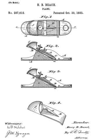
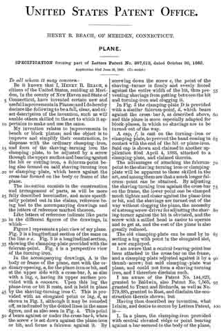
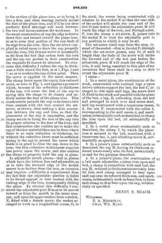
Be it known that I, HENRY B. BEACH, of Meriden, in the county of New Haven and State of Connecticut, have invented a new Improvement in Joiners’ Planes; and I do hereby declare the following, when taken in connection with accompanying drawings and the letters of reference marked thereon, to be a full, clear, and exact description of the same, and which said drawings constitute part of this specification, and represent, in —

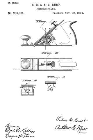
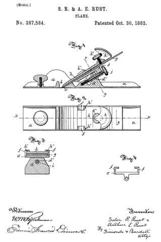
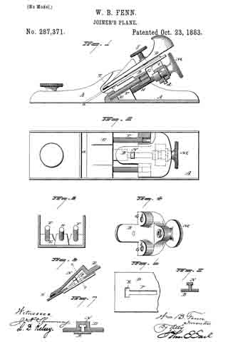
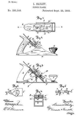
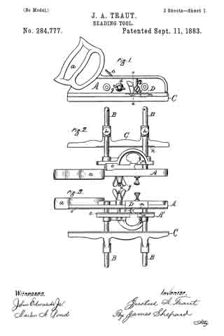
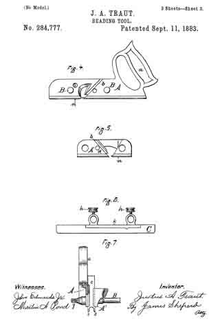
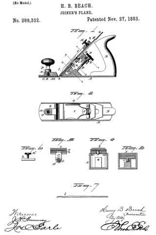
Figure 1, a sectional side view; Fig. 2, a top view; Fig. 3, a transverse section on line x x; Fig. 4, a transverse section on line y y; Fig. 5, a transverse section on line z z; Fig. 6, a transverse section through the clamping-bar h; Fig. 7, an edge view of the cap.

This invention relates to an improvement in that class of planes for joiners’ use in which the stock is made from cast metal, the object of the invention being a simple, ready, and positive adjustment and firmness of the plane-iron when once it is set in the required position; and the invention consists in the construction, as more fully hereinafter described, and particularly recited in the claims.

A represents the stock, made from cast-iron, fitted with the usual handle, B. Upon the inner surface of each side of the stock is a ledge, a, inclined in a line from the mouth, according to the pitch required for the plane-iron. These ledges form supports for the bed C, and on the upper surface of which the bed rests — that is to say, the bed lies upon these inclines. Below these inclined bearings a, and centrally between the two sides, a screw-stud, D. is set in a plane parallel with the inclines both vertically and horizontally, as seen in Fig. 1. From the under side of the bed a lug, E, extends downward, with an opening through it corresponding to the screw-stud D, and so as to pass freely over the stud.

F is a nut fitted to the screw-stud, and carrying a collar, b. The lug is recessed transversely to form a slot, d, to receive the collar b of the nut, and so that in placing the bed in its position the nut is first set into engagement with the slot d, then the bed moved down to carry the lug over the screw-stud, and so as to permit the nut to engage the screw; then turning the screw in one direction will move the bed downward, and in the reverse will draw it upward.

On the bed C the plane-iron G is placed, and over this the clamp H, and then upon that the clamp I, which is secured by a set-screw, K. The arrangement of the clamp whereby the plane-iron is secured to the bed may be any of the usual constructions.

As here represented, a headed stud, L, attached to the clamp I, passes through beneath the cap and iron and engages a slot in the bed below, so as to form a fulcrum for the clamp. Then the point of the clarnp bears upon the iron, the power being applied through the screw K to force the point into its clamping position — a usual and well-known construction. The bed is held down at its lower end by an L-shaped lug, e, engaging a corresponding L-shaped flange, f, on the stock. (See Figs. 1 and 5.)

In the usual construction of this class of clamps the screw is inade to bear at a central point and over a comparatively small surface. Unless the corresponding surfaces of the bed and plane-iron make a perfect fit between the two, the iron is easily thrown out of adjustment. To increase this bearing-surface of the adjusting-screw, I arrange a bar, h, in a slot transversely across on the under side of the head of the clamp, and it should be in length nearly the width of the plane-iron. This is engaged with the set-screw by upsetting the screw upon the under side of the bar, as seen in Figs. 1 and 6, but so as to leave the screw free to turn in the bar; hence by turning the screw in one direction the bar will be drawn into the slot, and turned in the opposite direction will be forced downward. This transverse bar affords a long surface of bearing upon the plane-iron, and so that the force of the screw is applied to that entire surface; hence so broad or extended a bearing upon the plane-iron is attained as to prevent the possibility of accidental displacement. In this class of planes in which a cap is employed in connection with the plane-iron a ditliculty is experienced in properly fitting the edge of the cap to the surface of the plane-iron, or to bring it into a firm and close bearing entirely across the face of the plane-iron, and if it be not thus perfectly fitted shavings will work between the two and inconvenience the workman. In the usual construction of cap the edge is drawn down thin and turned toward the plane-iron, so as to raise that portion of the cap back of its edge from the iron; then the set-screw i applied is relied upon to draw the cap properly onto the iron; but this set-screw is necessarily so far from the foot that unless both the iron and the cap are perfect in their construction the requisite fit cannot be attained. To overcome this difficulty I reduce the cap in thickness a little above the foot, as at l, Figs. 1 and 7 , so as to weaken the cap at that point. Then the screw is applied in the usual manner. The clamp bears upon the cap at this reduced point, as seen at Fig. 1, and applies a pressure which, because of the reduction in thickness of the cap, will cause the foot of the cap to spring into the shape to fit closely and entirely across the face of the plane-iron. This construction permits the cap to be drawn into close contact with the iron around the set-screw, as shown, thus making a firm connection between the cap and iron, so that dis-
placement of the cap is impossible, and the clamp serves to bring the foot of the cap into its proper relation to the face of the iron; and this construction also enables me to make the cap of thicker material than can be done where there is no such reduction in thickness, for without the reduction there must be sufficient spring in the cap to permit the screw which holds it in place to draw the cap down to the iron; but this reduction in thickness requires less power upon the screw, and also enables the clamp to properly hold the cap in place.

In adjustable mouth planes — that is, planes which have the bottom fore end adjustable, so as to take the forward edge of the mouth nearer to or farther from the iron, as occasion may require – a difliculty is experienced from the fact that the adjustable portion is liable to be forced against or into contact with the cutting-edge of the iron, consequently drilling the plane. To obviate this difficulty I construct the adjustable part M so as to be moved toward or from the mouth in the usual manner, and upon its upper surface form a socket, N, fitted with a female screw, the socket arranged to work in a longitudinal recess, O, in the stock, the recess being constructed with relation to the socket N so that the rear side of the socket will strike the rear end of the slot O just before the adjustable piece M will reach the edge of the iron, and through a slot, P, into the recess a set-screw, R, passes into the socket N to bind the adjustable part in any position to which it may be set.

The set-screw itself may form the stop, instead of the socket — that is, the slot P, through which the set-screw passes, may be of such length that the body of the screw will strike the forward end of the slot just before the adjustable piece M will reach the edge of the iron, it only being essential to this part of my invention that there shall be a stop to thus arrest the adjustable piece M.

I claim —

1. In a metal plane, the combination of the stock, constructed with inclined lugs a upon its two sides to support the bed, the bed C, arranged to ride upon said lugs, the screw-stud D, fixed in the stock and parallel with the plane of the bed, a lug, E, extending from the bed and arranged to work over said screw-stud, said lug constructed with a transverse recess, d, the nut F, constructed with the collar b, corresponding to the said recess d, and mechanism, substantially such as described, to clamp the iron upon the bed, all substantially as specified.

2. In a metal plane substantially such as described, the clamp I, by which the plane-iron is secured to the bed, combined with a transverse bar, h, and adjusting-screw K, substantially as specified.

3. In a joiner’s plane substantially such as described, the cap H, having its thickness reduced transversely near its foot, substantially as and for the purpose described.

4. In a joiner’s plane, the combination of a bed made adjustable, a plane-iron upon said bed, a clamp in connection with said bed, the cap H, reduced in thickness transversely near its foot, said clamp arranged to bear upon said cap near its reduced thickness, and mechanism, substantially such as described, to force said clamp to thus bear upon the cap, substantially as specified.

HENRY B. BEACH.

Witnesses:
E. A. MERRIMAN,
CHAS. WM. MANN.

No. 288,866 – Joiner’s Plane (Solon R. Rust And Arthur E. Rust) (1883)

[paiddownloads id=”347″]288866


UNITED STATES PATENT OFFICE.

_________________

SOLON R. RUST AND ARTHUR E. RUST, UF PINE MEADOW, CONNECTICUT, ASSIGNORS TO SAID
SOLON R. RUST, AND HENRY B. BEACH AND JOHN C. BEACH, BOTH OF MERIDEN, CONNECTICUT.

JOlNER’S PLANE.

_________________

SPECIFICATION forming part of Letters Patent No. 288,866, dated November 20, 1883.
Application filed September 10, 1883. (No model.)

_________________

To all whom it may concern:

Be it known that we, SOLON R. RUST and ARTHUR E. RUST, of Pine Meadow, county of Litchfield, State of Connecticut, have invented an Improvement in Joiners’ Planes, of which the following is a specification.

This invention relates to an improvement in that class of joiners’ planes in which the stock is constructed from metal, usually cast-iron.

In the more general construction of this class of planes the bed to which the plane-iron is clamped is arranged in guides or bearings formed in the sides of the stock. These require to be planed with great exactness, and the bed to be correspondingly fitted.

The object of our invention is to simplify the construction of the plane, so far as the fitting and guiding of the bed are concerned; and it consists in the arrangeinent of a guiding stud or studs in the stock, midway between its two sides, and on an incline corresponding to the inclined position required for the bed, which stud or studs serve as guides for the support and movement of the bed, and having cornbined therewith an adjusting-screw arranged in a plane parallel with the said stud or studs, and as more fully hereinafter described.

In the accompanying illustration, which forms part of this specification, Figure 1 represents a longitudinal section on line z z; Fig. 2, a top view; Fig. 3, a transverse section on line x x, and Fig. 4 a transverse section on line y y.

A represents the stock, of the usual form, provided with a handle, B. C is the bed on which the iron D rests, and is clamped by means of the cap E, the cap E provided with lugs as near its upper end, which pass under and embrace the bed, as seen in Fig. 3, the set-screw F serving to bring the point of the cap onto the iron near its edge, and so as to clamp the iron firmly to the bed; but this arrangement of clamping is immaterial to this invention, as the cap may be applied in any of the usual or well-known methods.

In the stock beneath the bed a stud, G, is arranged in a plane parallel with the position required for the bed. This stud is best set by drilling into the stock and setting a stud of the required diameter therein, as seen in Fig. 1. On the under side of the bed is a lug, H, at right angles to the bed, and through which a hole is bored corresponding to the stud G, and so as to pass thereon and move freely toward or from the mouth of the plane, the stud serving as a guide for such increment of the bed. This stud, placed centrally, as seen in Fig. 4, permits the bed to rock iroin right to left to adapt itself to the position of the plane-iron. The plane-iron, near the mouth b, takes a bearing on the stock, as at d, which gives the proper transverse position for the plane-irons. The bed will therefore adapt itself to this position of the stud. The lug H extends below the pivot and engages with an adjusting-screw, I. This adjusting-screw is threaded to tit a corresponding screw-hole, e, in the stock, and in a plane parallel with the axis of the stud G. This screw is provided with a collar, f, which engages a slot, l, in the lug H, and so that turning the screw in one direction forces the bed and the iron to more downward, and in the opposite direction upward, and whereby the edge of the iron may be set in the proper relation to the face of the plane. The stud G may be of sufficient length to take a bearing near the two ends of the bed, but we prefer to introduce a second stud, L, into the stock below, as seen in Fig. 1, for the support of the bed below; or two studs may be introduced, one parallel with the other and in the same plane horizontally, which will give two supports for the bed; but in such arrangement of studs the advantage of the rocking movement is not attained.

The introduction of the diagonal guiding-studs into the stock beneath the bed is much cheaper than the usual inclined side guides formed upon the inner surface of the sides of the stock.

What we claim as our invention is —

In a metal plane, the combination of the stock provided with one or more inclined studs, G, beneath the bed, the bed constructed with a. downwardly-projecting lug, H, constructed to ride on said stud as a support and guide, a screw arranged in the stock parallel with said stud and in engagement with the bed, the plane-iron, cap, and means, substantially such as described, for clamping the plane iron to the bed, all substantially as described.

SOLON R. RUST.
ARTHUR E. RUST.

Witnesses:
GEO. H. RICE,
EDW. E. KELLOGG.

No. 287,612 – Plane (Henry B. Beach) (1883)

[paiddownloads id=”346″]287612


UNITED STATES PATENT OFFICE.

_________________

HENRY B. BEACH, OF MERIDEN, CONNECTICUT.

PLANE.

_________________

SPECIFICATION forming part of Letters Patent No. 287,612, dated October 30, 1883.
Application filed June 21, 1883. (No model.)

_________________

To all whom it may concern:

Be it known that I, HENRY B. BEACH, a citizen of the United States, residing at Meriden, in the county of New Haven and State of Connecticut, have invented certain new and useful Improvements in Planes; and I do hereby declare the following to be a full, clear, and exact description of the invention, such as will enable others skilled in the art to which it appertains to make and use the same.

My invention relates to improvements in bench or block planes; and the object is to improve and simplify their construction, to dispense with the ordinary clamping-iron, and form of the shaving-turning iron the clamping-plate, to be adjusted by a screw through the upper surface and bearing against the bit or cutting-iron, a fulcrum-point being also formed on said shaving-turning iron or clamping-plate, which bears against the cross-bar formed on the body or frame of the plane.

The invention consists in the construction and arrangement of parts, as will be more fully described hereinafter, and more specifically pointed out in the claims, reference being had to the accompanying drawings and the letters of reference marked thereon.

Like letters of reference indicate like parts in the different figures of the drawings, in which —

Figure 1 represents a plan view of my plane. Fig. 2 is alongitudinal section of the same on the line x x. Fig. 3 is a longitudinal section, showing the clamping-plate provided with the fulcrum-point. Fig. 4 is a perspective view of the turning-iron.

In the accompanying drawings, A is the body or frame of the plane, cast with the ordinary opening, a, for the plane-iron or bit, and at the upper side with a cross-bar, b, as also with a lug, c, having its upper surface provided with a concave. Upon this lug the plane-iron or bit B rests, and is held in place by the shaving-turning iron C. This is provided with an elongated point or lug, d, as shown in Fig. 1, although it may be rounded off, as indicated by the dotted lines in the same figure, and as also seen in Fig. 4. This point d bears against or under the cross-bar b, when the screw e is set down against the plane-iron or bit, and forms a fulcrum against it. By screwing down the screw e, the point of the shaving-turner is firmly and evenly forced against the entire width of the bit, thus preventing shavings from getting between the bit and turning-iron and clogging it.

In Fig. 3 the clamping-plate D is provided with a similar fulcrum-point, d, which bears against the cross-bar b, as described above, and this plane is more especially adapted for block-planes, in which no shavings are to be turned out of the way.

A cap, f is cast on the turning-iron or clamping-plate, to prevent the hand coming in contact with the end of the bit or plane-iron. Said cap is shown and claimed in another application filed April 4, 1883, attached to a clamping-plate, and claimed therein.

The advantages of attaching the fulcrum-point to the shaving-turning iron or clamping-plate will be apparent to those skilled in the art, and among them are that a much longer fulcrum-point can be obtained. By adjusting the shaving-turning iron against the cross-bar on the frame, the lower point can be clamped much tighter and closer against the plane-iron or bit, and the shavings are turned out of the way without clogging the plane, the necessity of a strong screw-driver for adjusting the shaving-turner against the bit is obviated, and the screw with a milled head is easier to operate and to get at, and the cost of the plane is also greatly reduced.

The old clamping-plate can be used by inserting a lug with point in the elongated slot, as new employed.

I am aware that a central bearing-point has been attached to the cross-bar on the frame, and a clamping-plate adjusted against it by a thumb-screw; but said clamping-plate was plane, and could not form a shaving-turning iron, and I therefore disclaim such.

I am aware of the Patent No. 144,823, granted to Baldwin, also Patent No. 7,565, granted to Traut and Richards, as well as No. 279, 885, granted to Rust, and disclaim the construction therein shown; but

Having thus described my invention, what I claim, and desire to secure by Letters Patent, is —

1. In a plane, the clamping-iron provided with central elevated ridge or point bearing against a bar secured to the body of the plane, so that in adjusting said iron. it will bear uniformly on the planing-iron, substantially as shown and specified.

2. In a plane, the clamping-iron provided with central elevated ridge or point bearing against the lower side of a transverse bar secured to the body of the plane, and adjusted by a screw bearing against the plane-iron, and uniformly pressing against said plane-iron at its lower end, to form a, shaving-turner, substantially as set forth.

In testimony whereof I hereby affix my signature in presence of two witnesses.

HEHRY E. BEACH.

Witnesses:
L. F. KELEHER,
J. M. YZNAGA.

No. 287,584 – Plane (Solon R. Rust And Arthur E. Rust) (1883)

[paiddownloads id=”345″]287584


UNITED STATES PATENT OFFICE.

_________________

SOLON R. RUST AND ARTHUR E. RUST, OF PINE MEADOW, CONNECTICUT.

PLANE.

_________________

SPECIFICATION forming part of Letters Patent No. 287,584, dated October 30, 1883.
Application filed May 10, 1883. (Model.)

_________________

To all whom it may concern:

Be it known that we, SOLON R. RUST and ARTHUR E. RUST, of Pine Meadow, in the county of Litchfield and State of Connecticut, have invented certain new and useful Improvements in Planes, of which the following is a description, reference being had to the accompanying drawings, where —

Figure 1 is a view in longitudinal vertical section of a plane embodying our improvements on plane denoted by line x x of Fig. 2. Fig. 2 is a top view of the same. Fig. 3 is a detail view in cross-section on the line y y of Fig. 1. Fig. 4 is a detail end view of the carriage, looking from below.

Our invention has for its object the construction of planes cheaper and more readily adjusted to varied uses than the forms now in common use; and it consists in the special arrangement and combination of the parts for adjusting the cutting-iron and clamping the same, and in changing the character of the plane from a single to a double iron, as hereinafter more particularly described.

In the accompanying drawings, the letter a denotes a body of common form, and made of any desirable material, as iron; b, the usual mortise or opening through to the face of the plane; c, the cutting-bed; d, a transverse flange provided with the socket d’; e, a carriage having upon the lower side a tubular projection adapted to fit into and move longitudinally in the socket d’, and on its upper side the arms f, provided with the interiorly-projecting flanges or their equivalents.

On the carriage, and between the arms, rests the cutting-iron g, which is a flat piece of metal provided with a chisel-edge, and upon it, and also adapted to slide between the arms, is arranged the cap-iron and clamp h, which has upon each side the projections h’, which limit the forward movement of the clamp, and at its rear end, in a threaded socket, the clamp-screw h”.

The screw spindle i is rotarily secured in the tubular projection on the carriage, as by means of the transverse pin j, and its lower end projects into and operates in the nut formed in the body of the plane. This peculiar arrangement of the carriage enables it to have a rocking motion sidewise, or transversely of the plane, and at the same time makes it adjustable in the plane of the cutting-iron. This rocking motion of the carriage enables one to adjust the back of the plane-iron to a perfect bearing on the cutting-bed, and at the same time support and hold it against longitudinal motion.

The cap-iron is made to serve as a clamp by its lower edge, resting upon the cutting-iron near its lower end, passing under the flanges on the arms, which serve as fulcrums, and by being raised from the cutting-iron near the upper end by means of the clamp-screw, the lower end of which takes against the face of the iron. It serves the purpose of the ordinary cap-iron, when desired, and at the same time can be readily slipped back, leaving the plane in the form known as “single-iron” planes.

One peculiar and important feature of our invention consists of the combination of cap-iron and clamp, so arranged that the relative positions of the cutting-edge of the iron and the front edge of the clamp are not changed when the iron is adjusted to fix the thickness of shaving to be cut by the plane. The smoothness of the surface left after removing a shaving is determined by this relative position of cutting-edge of iron and edge of cap-iron, and once fixed in our device it remains constant, as described, while the thickness of the shaving may be varied by the adjustment of the carriage. This construction of parts is a great saving in expense over the ordinary method of arranging and combining the cutting-iron and the cap-iron, and possesses the further advantage of simplicity and ready adjustment to various uses.

The thickness of the shaving made by the plane is adjusted by means of the screw-spindle, which has a suitable head for operating with the thumb and finger.

In order to enable the tubular projection to slide readily, or to rock in the socket d’, we slab off, as seen in Fig. 3, portions of its upper surface, to decrease the bearing-surface within the socket. This, however, is not essential to the perfect operation of our device, as the carriage may have a downward projection resting in a guide-groove in the plane-body, or be adapted to rock in many ways obvious to the skilled mechanic on slight inspection of our device.

We claim as our invention —

1. In combination, a plane-body having a socket, and the carriage having at longitudinal reciprocation and also an transverse rocking motion in said socket, with means for adjusting said carriage, all substantially as described.

2. In combination, the plane-body, the carriage having a longitudinal motion and also a transverse rocking motion, and bearing the plane-iron and combined cap-iron and clamp, all substantially as described.

3. In combination with a plane-body and a carriage, substantially as hereinbefore described, the plane-iron and combined cap-iron and clamp, made, in one piece, the relative position of the two latter parts remaining unchanged when the plane-iron is adjusted to determine the depth of cut of the iron, all substantially as described.

SOLON R. RUST.
ARTHUR E. RUST.

Witnesses:
A. C. TANNER,
WM. H. MARSH.

No. 287,371 – Joiner’s Plane (William B. Fenn) (1883)

[paiddownloads id=”344″]287371


UNITED STATES PATENT OFFICE.

_________________

WILLIAM B. FENN, OF MERIDEN, CONNECTICUT,
ASSIGNOR TO FOSTER MERRIAM & CO., OF SAME PLACE.

JOINER’S PLANE.

_________________

SPECIFICATION forming part of Letters Patent No. 287,371, dated October 23, 1883.
Application filed June 30, 1883. (No model.)

_________________

To all whom it may concern:

Be it known that I, WILLIAM B. FENN, of Meriden, in the county of New Haven and State of Connecticut, have invented a new Improvement in Joiners’ Planes; and I do hereby declare the following, when taken in connection with accompanying drawings and the letters of reference marked thereon, to be a full, clear, and exact description of the same, and which said drawings constitute part of this specification , and represent, in —

Figure 1, a sectional side view; Fig. 2, a top view, with the plane-iron and clamp removed; Fig. 3, a rear view, the bed removed, showing the inclined guiding-sides and screw. Fig. 4, a perspective view of the bed removed, looking toward the under side; Fig. 5, a longitudinal section of the clamp through the T-shaped slot; Fig. 6, an under side view of the clamp; Fig. 7, a transverse section of the clamp on line x x of Fig. 5; Fig. 8, a transverse section of the bed, showing the T-shaped stud.

This invention relates to an improvement in that class of joiners’ or bench planes in which mechanism is employed to adjust the cutter with relation to the thickness of the shaving to be cut. In the more general construction of this class of planes the bed is fitted to work upon ways in the stock. These ways, as well as the bed, require to be shaped or fitted in the planing-machine, and this fitting of the bed and ways is an expensive part of the manufacture of the plane.

The principal object of my invention is to avoid this expensive part of the work; and the invention consists in the construction of plane as hereinafter described, and more particularly recited in the claims.

A represents the stock, which is of substantially the usual form; B, the bed upon which the plane-iron or cutter C is supported; D, the clamp by which the iron is secured upon the bed. E is the rest or support for the lower part of the plane-iron, and which terminates at the throat a.

The surface of the bed and the surface of the rest E must be in substantially the same inclined plane. In the rear end of the rest E, I introduce studs F F, projecting therefrom, and upwardly inclined in a plane parallel with the plane of the bed and rest. These studs are best made from round rods cut to the required length, and driven into corresponding holes in the rest.

The bed B is constructed with downwardly-projecting cars G, through which holes b are made corresponding to the studs F F, and so that the bed set upon the studs F will move freely thereon as guides, and the bed be retained in its proper relative position to the rest. The employment of these studs as guides is very much cheaper than the planed seat hitherto generally employed, as the holes for the studs as well as the corresponding holes in the bed are readily drilled by a pair of drills arranged for the purpose, so that the relative position of the two parts is assured.

To adjust the bed, a third stud, H, is arranged in the rest between the studs F F. This stud is screw-threaded, and in a lug, I, which extends down from the bed, a nut, L, is arranged. This nut is free for rotation, but prevented from longitudinal movement (here represented as so prevented) by a screw, d, through the lug into a corresponding annular groove in the body of the nut. The nut is fitted at its outer end with a head, M, by which it may be conveniently turned. The nut is internally threaded, corresponding to the stud H, and so that by turning the nut the bed will be moved accordingly.

Instead of two studs a single stud may be employed and accomplish a good result. I do not limit this part of my invention, therefore, to the employment of the two studs F F.

To engage the clamp with the bed, I construct the bed with an upwardly-projecting T-shaped stud, N, which will pass through the central slot in the plane-iron, so that the iron may be placed upon the bed and rest. The clamp D is constructed with a longitudinal slot, P, T- shaped in transverse section, as seen in Fig. 7. This slot is inclined from the lower end backward and upward from the plane of the under side of the plate, the opening of the slot being upon the under side.

The head of the stud N enters the lower end, R, of the slot, and then, as the clamp is forced downward, the inclined T part of the slot engages the shoulder of the stud N, as seen in Figs. 5 and 7, the incline acting as a wedge to draw the clamp down upon the plane-iron, and thereby serve to clamp the iron to the bed, and so that a quite firm engagement may be made by simply thus forcing the clamp downward; but to make a firm engagement a set-screw, S, through the clamp is provided, to bear upon the iron above the point where the stud N engages, and so that the stud forms a fulcrum upon which the clamp will act as a lever, its forward or lower end bearing upon the iron below the stud and the screw above.

Instead of making the inclined slot in the clamp and fixing the stud to the bed, this order may be reversed, and the inclined slot made in the bed and the stud fixed to the clamp. In such construction, it will be understood the incline will be reversed — that is, so as to draw the clamp toward the bed by the downward movement of the clamp.

Considerable difficulty is experienced in the use of this class of planes, from the fact that the great resistance offered to the working of the plane — as, for instance, in striking a knot — tends to turn the iron out of its proper position, the natural friction between the clamp and bed not being sufficient to hold the iron. To overcome this difiiculty, I apply to the clamp a facing, T, of non-metallic material, preferably of india-rubber. This is best made by the introduction of a strip of rubber across the lower end of the clamp, as seen in Fig. 1; but it may be applied at other positions, and advantageously so, at about the point where the screw bears — that is, an india-rubber or other non-metallic shoe may be applied to the lower end of the screw to bear upon the surface of the plane-iron — or this non-metallic bearing-surface may be arranged upon the bed, or upon the rest beneath the plane-iron; or it may be applied both to the clamp and to the bed, it only being essential to this part of my invention that there shall be a non-metallic bearing-surface for the plane-iron.

I claim —

1. In a plane substantially such as described, the combination of one or more inclined guiding-studs, F, fixed in the stock, the bed B, constructed to ride upon said inclined stud, mechanism, substantially such as described, to hold the plane-iron upon the bed, an inclined adjusting-screw and nut whereby said bed and the iron which it carries are made adjustable upon said stud, substantially as described.

2. In a plane substantially such as described, the combination of one or more inclined guiding-studs, F, the correspondingly-inclined screw-stud H, the bed B, constructed to ride upon said inclined stud, and the nut L, arranged in said bed, fixed as to longitudinal movement but free for rotation, substantially as described.

WILLIAM B. FENN.

Witnesses:
JOS. C. EARLE,
J. H. SHUMWAY.

No. 286,894 – Plane (Fortune L. Bailey) (1883)

[paiddownloads id=”343″]286894


UNITED STATES PATENT OFFICE.

_________________

FORTUNE L. BAILEY, OF FREEPORT, INDIANA.

PLANE.

_________________

SPECIFICATION forming part of Letters Patent No. 286,894, dated October 16, 1883.
Application filed July 12, 1883. (No model.)

_________________

To all whom it may concern:

Be it known that I, F. L. BAILEY, of Freeport, in the county of Shelby and State of Indiana, have invented certain new and useful Improvements in Planes; and I do hereby declare the following to be a full, clear, and exact description of the invention, such as will enable others skilled in the art to which it pertains to make and use it, reference being had to the accompanying drawings, which form part of this specification.

My invention relates to an improveinent in planes; and it consists, first, in the combination of the bearing-plate having the adjusting-screw swiveled thereto, the slotted bit which is attached by means of a set-screw to the plate which bears against its top, and a screw-bolt which passes through both of the plates and the bit, and which has the adjusting-screw to pass through its lower end; second, in a bit having a nut passed through its outer end, and a set-screw passed through the nut, so as to have its lower end bear against the lower plate, and thus adjust the angle at which the bit shall set, as will be more fully described hereinafter.

The object of my invention is to provide an attachment for the bits of planes, whereby the bit can be adjusted back and forth and set it at any desired angle without having to remove the bit from the plane-stock.

Figure 1 is a longitudinal vertical section of a bit embodying my improvements. Fig. 2 is an inverted view of the same.

A represents the lower or bearing plate, which has the lug B formed on the lower side of its outer end, and in which the adjusting-screw C is swiveled. This screw will be of any desired length, and is used to adjust the bit and the plate placed upon its top back, and forth in relation to the plate A. Through this plate A is made a vertical slot, D, of any desired length, and through which passes the screw-bolt E. This screw-bolt E has an enlarged perforated head upon its lower end, for the adjusting-screw to pass through, and receives a thumb screw or nut, F, upon its upper end, for the purpose of clamping the parts of the attachment tightly against the bit. The bit G also has a slot cut through it; but it need not necessarily be as wide nor as long as the one which is cut through the plate A. Through this slot is passed the bolt and the set-screw H, which secures the bit and the top plate, I, together. This top plate, I, and the bit are secured rigidly together by means of this set-screw, for the purpose of causing them to move together when the adjusting-screw is turned. The top plate may either rest solidly upon the bit, or it may be made in the form of a spring, as may be desired. Through the outer end of the bit is passed a nut or bushing, J, through which is passed the set-screw L. By means of this set-screw L the bit can be set at any desired angle in relation to the part A. Secured to the under side of the bearing-plate A is a suitable bracket, O, to rest on the top of the plane-stock when made of wood.

By means of the construction here shown and described, the bit may be adjusted back and forth without having to remove the parts from the plane.

I am aware that a slotted bit has been adjusted by means of screw-rods and nuts, which project up from the side of the body of the plane, and which rods have a connecting-plate passed over them, so as to bear against the outer end of the bit, and thus feed it forward, and this I disclaim. My invention differs from this in having the adjusting-screw swiveled directly upon the bearing-plate A, and which is made to adjust the bit by means of a screw-bolt which passes through the plate placed upon the top of the bit and the bit itself.

Having thus described my invention, I claim —

1. In a plane, the combination of the plate A, which is attached to the under side of the bit, with the inclined bracket O, which is secured to the under side of the plate, substantially as shown.

2. The combination of the bearing-plate A, which is secured to the under side of the bit G, and which plate is provided with the slot D, with the swiveled adjusting-screw C, which is attached at its outer end to the plate A, the screw-bolt E, which passes through the slots in the bit, the bit provided with the slot for the bolt to pass through, and the plate placed upon the bit, substantially as described.

3. The combination, with the bit, of a nut or bushing which is passed through its outer end, and the set-screw which is passed through the nut or bushing for the purpose of adjusting the inclination of the bit, substantially as specified.

4. The combination of the bearing-plate provided with a slot, the slotted bit, the set-screw, the plate which is placed upon the top of the bit, the screw-bolt which passes through both of the plates and the bit, the adjusting-screw for moving the bit back and forth, and the set-screw for regulating the angle at which the bit is placed, substantially as shown.

In testimony whereof I affix my signature in presence of two witnesses.

FORTUNE LEWIS BAILEY.

Witnesses:
MARCUS B. CHADWICK,
LEVI W. WHITE.

No. 285,546 – Bench-Plane (Leonard Bailey) (1883)

[paiddownloads id=”342″]285546


UNITED STATES PATENT OFFICE.

_________________

LEONARD BAILEY, OF HARTFORD, CONNECTICUT.

BENCH-PLANE.

_________________

SPECIFICATION forming part of Letters Patent No. 285,546, dated September 25, 1883.
Application filed July 11, 1883. (No model.)

_________________

To all whom it may concern:

Be it known that I, LEONARD BAILEY, of Hartford, in the county of Hartford and State of Connecticut, have invented certain new and useful Improvements in Planes; and I do hereby declare that the following is a full, clear, and exact description thereof, whereby a person skilled in the art can make and use the same, reference being had to the accompanying drawings, and to the letters of reference marked thereon.

Like letters in the figures indicate the same parts.

Figure 1 is a plan view of the upper side of the plane in a line at right angles to the plane of the iron parts broken away. Fig. 2 is a side view of a plane having my improvement. Fig. 3 is a view in central vertical longitudinal section of same on line x x of Fig. 1. Fig. 4 is a view in cross-section on plane denoted by line y y of Fig. 3. Fig. 5 is a detail bottom view of my improved clamp. Fig. 6 is a detail side view of same.

My invention relates to the class of devices used for holding the cutting-iron of a plane in place in the body in such manner as to allow of the ready adjustment of the iron lengthwise in the usual manner.

It consists in the special combination and arrangement ofthe parts making up the clamping device, and in the method of fastening it in the plane-body.

In the accompanying drawings, the letter a denotes the plane-body as a whole, formed of any ordinary material, as iron; b and c, handles for grasping and using the plane; d, a cutting-iron of ordinary form arranged upon a bed, e, so as to be protruded from the usual mortise, f, by means of any slow-motion device, as a series of intermeshing cog-wheels, g, operated by means of the thumb-screw h.

There is nothing new or original with me in the parts described thus far, and no further description is needed for one skilled in making or using planes.

In the style shown the plane-body a is of iron, with the upright side flanges, a’ a”, and on the inner side of each of these danges the corresponding mortises, k k’, are made substantially parallel in direction with the plane of the cutting-iron, and a short distance above or in front of its upper surface.

The letter l denotes the clamp-plate, having the foot l’, adapted to bear upon the face of the cutting-iron, or on the cap-iron d’, placed just over and upon it, and having arranged upon its under side, just in front of a transverse shoulder, the laterally-projecting arm m, adjustably attached to the clamp-plate by means of the screw n. This arm is so arranged that its opposite ends fit into and move in the mortises in the flanges, and form the fulcrum on which the clamp works in fastening the irons in place. In the upper end of the clamp-plate is placed a clamp, o, consisting of a shaft, o’, which is rotarily secured with its lower end bearing upon the cutting-iron about on its center line, and bears the lever p, which extends beyond the edges of the clamp-plate, and operates in connection with the face-cam r on its under side.

The particular object of my invention is to secure a firm and even bearing for the foot of the clamp upon the irons under it, to provide simple means for regulating the pressure of the clamp at will, and yet have it constant for any given set of irons, and have all the requisite parts simple in form, combination, and operation.

The arm m is loosely attached to the clamp-plate, so that the foot of the latter may find a bearing for its whole length on the iron under it, and the ends of the arm at the same time bear upon the sides of the mortises when the clamp-plate is clamped.

The clamp-plate and arm may be connected, so that the arm will tilt or work by means of a rivet or short bolt; but I prefer to use the screw herein shown and described, as I can then adjust the amount of pressure put upon the parts in clamping the irons in place, and vary it as the parts wear, or for different irons adapted to the same body.

In the drawings the clamp is shown as locked; but it is unlocked by turning the lever about ninety degrees to the position shown in dotted lines in Fig. 1, as this allows the shaft to slip upward through the clamp as the lever moves along the cam. By pulling straight back, the clamp may be removed as the arms slide out of the mortises. By means of the screw n the arm is raised or lowered with respect to the clamp-plate and the binding force of the shaft-lever and cam is adjusted.

I am aware that clamp-plates bearing cam devices for fastening the irons in place are not new, and these I do not broadly claim.

I claim as my invention —

1. In combination, the plane-body having the side flanges with inward-facing mortises, and the clamp-plate bearing the loosely-attached arin, adapted to operate in said mortises and the clamp, all substantially as described.

2. In combination, the mortised plane-body, the clamp-plate bearing the adjustable arm attached thereto by the centrally-located screw, and having the face-cam, and the rotary shaft bearing the lever operating on said cam, all substantially as described.

3. In combination, in a plane having the lateral mortises or bearings, the clamp-iron bearing the loosely-connected arm arranged transversely of the clamp-iron, and adjacent to the arm, the shoulder, or its equivalent, whereby the arm is held against rotation, all substantially as described.

LEONARD BAILEY.

Witnesses:
CHAS. L. BURDETT,
E. F. DIMOCK.

No. 284,941 – Rabbet-Plane (John M. Bennett) (1883)

[paiddownloads id=”341″]284941


UNITED STATES PATENT OFFICE.

_________________

JOHN M. BENNETT, OF GREEN ISLAND, NEW YORK, ASSIGNOR TO
HENRY C. BAILEY, OF COVINGTON, KENTUCKY.

RABBET-PLANE.

_________________

SPECIFICATION forming part of Letters Patent No. 284,941, dated September 11, 1883.
Application filed August 18, 1882. (No model.)

_________________

To all whom it may concern:

Be it known that I, JOHN M. BENNETT, a citizen of the United States, residing at the village of Green Island, in the county of Albany and State of New York, have invented new and useful Improvements in Rabbet-Planes, of which the following is a specification.

My invention relates to improvements in rabbet-planes; and the objects of my improvements are to provide a strong and durable stock and base or bed-piece of suitable metal, having a cutter adjusted by means of a cap and screw, and also a guide or fence, so that it can be used with either hand and as a fillister. I attain these objects by the mechanism illustrated in the accompanying drawings, in which —

Figure 1 is a view in perspective of the plane complete. Fig. 2 is a view in perspective of the guide or fence. Fig. 3 is a view in perspective of the cap.

Similar letters refer to similar parts throughout the several views.

The stock L extends along the right side of the base or bed-piece A and at a right angle thereto, and has a suitable handle, O, at the rear end thereof. At a suitable point in the base or bed-piece A a throat is cut through and entirely across said base or bed-piece, into which throat the cutting-edge of the cutter B is placed and worked. Running from the rear side of the throat upward, upon a proper angle toward the rear of the stock, and cast thereon or fastened thereto, is the cutter-rest M, which is straight and flat, and upon which the cutter rests.

The cap C is a littler shorter than the cutter-rest M, and at the end placed near the throat is of the same width as thecutter, and is flat upon the under side and beveled to an edge upon the upper side. The under side of the cap C is flat and slightly concave to a point from the lower end for about two-thirds its length, from which point it is straight and inclined slightly upward. The upper side of said cap C is irregular in form, being the highest and narrowest at the point where the slot K is cut, and slightly convex from thence to the lower end and concave to the upper end. It is obvious, however, that any other form from the beveled end upward that will give a bearing at the slot K and lower end, and by means of the screw J at the upper end properly hold the cutter B in its position, may be used. Passing through the upper end of the cap C is a screw, J — a thumb-screw being the most convenient — the lower end of which is in contact with the upper side of the cutter B, and by means of which the pressure of the cap upon the cutter is regulated and the cutter held firmly in position or removed. At the highest point of the cap C, and upon the upper side thereof, is out crosswise a slot, K, to admit therein the lug or brace D, by means of which the cap is prevented from moving lengthwise. The lug or brace D is cast upon or fastened to the inside of the stock L, at a point about midway the throat and the upper end of the cutter-rest M, and projects over and a little beyond the center of said cutter-rest. Its size and shape are such as to be adapted to the use to which it is to be put. Through the stock L, at the front side of the throat, is cut a perpendicular slot, G, of any required width and length.

The guide E is a flat smooth piece, of suitable material and size, having firmly attached an upright, with a shoulder, F, made to fit and work in the slot G, and thus keep the base-piece of the guide always parallel to the base or bed-piece A. This guide is placed upon the outside of the stock K, and firmly fastened thereto by means of a screw, N, which passes through the slot G and into a suitable opening, having a corresponding thread cut therein, in the said upright. This guide may be raised or lowered at pleasure, and thus regulate the depth of the cut of the plane. A suitable opening is made through the stock L, extending a short distance upward from the throat in a line with the cutter, to allow the cuttings of the cutter to pass away from the throat, and this opening, as well as the throat, should be of such size and shape as are best adapted to a free and easy discharge of the cuttings of the cutter.

The cutter may be of much the same kind as those in ordinary use in planes. The lower or cutting end is of the same width as the face of the base or bed-piece A, and continues that width the length of the opening aforesaid in the stock L, and is from thence of about the same width as the cutter-rest M.

The handle O is of proper size and shape to fit the hand, and may be east as a part of and with the stock. Thus the base or bed-piece A, the stock L, handle O, lug or brace D, and cutter-rest M may all be cast of iron or other suitable metal, at one time and in one piece, forming a tool that will not warp or wear and work to a sharp corner. The size, of course, may be such as is required.

I am aware that prior to my invention rabbet-planes have been made. I therefore do not claim such plane, broadly; but

What I do claim as my invention, and desire to secure by Letters Patent, is —

In a plane, the stock L, having the slot G made through it, in combination with the guide E, provided with the flange F, and the set-screw H, for holding the guide in position, substantially as shown.

JOHN M. BENNETT.

Witnesses:
JNO. H. O’BRIAN,
PETER H. BUCKLEY.

No. 284,919 – Bench-Plane (William Steers) (1883)

[paiddownloads id=”340″]284919


UNITED STATES PATENT OFFICE.

_________________

WILLIAM STEERS, OF SHERBROOKE, QUEBEC, CANADA.

BENCH-PLANE.

_________________

SPECIFICATION forming part of Letters Patent No. 284,919, dated September 11, 1883.
Application filed January 25, 1883. (No model.)

_________________

To all whom it may concern:

Be it known that I, WILLIAM STEERS, a citizen of Canada, residing at Sherbrooke, in the county of Sherbrooke and Province of Quebec, Canada, have invented certain new and useful Improvements in Adjustable Composite Bench-Planes, of which the following is a specification, reference being had therein to the accompanying drawings.

This invention relates to improvements in bench-planes; and it consists in the devices for adjusting the cap upon the cutting-iron, the movements of the cutting-iron, and the closing of the throat of the plane to suit the different materials to be dressed, and also in the construction of the metallic body or frame of the stock, all of which will be hereinafter more fully described, and set forth in the claims.

In the drawings forming apart of this specification, Figure 1 is a longitudinal vertical section. Fig. 2 is an under side view of the face of the plane. Fig. 3 is a plan view of the plane-iron on top. Fig. 4 is a plan view of the cap. Fig. 5 is a transverse section on as so of Fig. 1.

A is a lever, pivoted at a, having at its lower end a segment-rack, a’, which meshes with a worm-gear, B, that is supported upon a proper bearing or standard, B’, within the stock of the plane A’, which is in this case secured by a screw, a”, through the bottom plate, A”. This bearing or standard B’ also supports the lever A, and forms a bed at b for the plane-iron I, against which it is pressed by the screw J.

In the plane-iron, on top, is a groove, H, for the foot of the screw J. In the plane-iron I there are holes i i i, into any one of which the small end a”’ of the lever A can be inserted; and below the lever A is one of the holes j, for the insertion of the end of a set-screw, D. Said screw works in a nut, C, below the cap K, and through the orifice d in the cap, for a purpose to be hereinafter explained.

J is a straining or clamp screw, which works in the nut k on the end of the cap-iron K.

G G are studs projecting on the inside of the stock-frame A’, to lock the cap-iron K.

E is a strong spring attached at top to a standard, E’, and its lower end, e, made as wide as the throat of the plane, and forming a casing for the front edge, e, of it.

e’ is an adjusting-screw by which the spring E is made to close the throat to such an adjustment as may be required to suit the character of the material to be dressed.

The adjusting worm-screw B is set in the standard B’ by means of a neck, c, and a retaining-pin, c’, which will allow the screw to be rotated, but prevents its withdrawal.

The bottom plate, A”, is formed with wide grooves F F, in which are inserted hard-wood strips F’ F’, as seen in section, Fig. 5.

The set-screw D is inserted in the hole j, and when the cap K has been properly adjusted to the plane-iron I, the screw D is then tightened, so that the nut C clamps the cap-iron K in its position; and by this device the plane-iron, when removed from the plane to be sharpened, will come to the same position each time, after being sharpened, without any further adjustment, as screw D will be dropped into the same hole each time.

The series of holes i i, &c. , in the plane-iron I is for the purpose of being used successively as the iron is ground away in sharpening, and they are at such a distance apart as to be accommodated to the other devices in connection therewith.

I claim —

1. In planes, the cap-iron K, provided with a slot, a set-screw having a free end passing through said slot, which enters the plane-iron, as shown, and a clamping-nut for fastening the screw at any point in the slot, substantially as and for the purpose described.

2. The cap-iron K, having a clamping-nut and screw, constructed as described, in combination with the plane-iron having a series of holes, andthe lever A, which enters one of said holes, substantially as described.

3. The combination of the spring-plate E, located in the throat of a plane, with the standard E’ and the adjusting-screw e’, substantially as and for the purpose described.

4. The metallic face-plate having longitudinal ribs and transverse ribs forming the throat of the plane, combined with wooden strips, as F’, inserted between the ribs, as set forth.

In testimony whereof I affix my signature, in presence of two witnesses, this 18th day of December, 1882.

WILLIAM STEERS.

Witnesses:
JOHN WILLIAMSON STOCKDALE,
J. D. JOHNSON.

No. 284,777 – Beading-Tool (Justus A. Traut) (1883)

[paiddownloads id=”339″]284777


UNITED STATES PATENT OFFICE.

_________________

JUSTUS A. TRAUT, OF NEW BRITAIN, CONNECTICUT, ASSIGNOR TO THE
STANLEY RULE AND LEVEL COMPANY, OF SAME PLACE.

BEADING-TOOL.

_________________

SPECIFICATION forming part of Letters Patent No. 284,777, dated September 11, 1883.
Application filed June 12, 1883. (No model.)

_________________

To all whom it may concern:

Be it known that I, JUSTUS A. TRAUT, a citizen of the United States, residing at New Britain, in the county of Hartford and State of Connecticut, have invented certain new and useful Improvements in Beading-Tools, of which the following is a specification.

My invention relates to improvements in beading-tools; and the objects of my improvements are the convenient adjustment for different sizes of cutters, and to make a cheap, efficient, and convenient tool especially adapted for forming beads. I attain these objects by the simple construction illustrated in the accompanying drawings, in which —

Figure 1 is a side elevation of my improved beading-tool. Fig. 2 is a plan view thereof. Fig. 3 is a reversed plan view. Fig. 4 is a side elevation of one part of the stock. Fig. 5 is a side elevation of the confronting face of the companion part of the stock. Fig. 6 is a side elevation of the gage; and Fig. 7 is a vertical section of my beading-tool on line x x of Fig. 1, the same being represented with the cutter as drawn up a little, in order to better show the lower working faces of the stock.

My beading-tool is designed for use by hand, the same as other bench-tools — such as plows, planes, &c. — and belongs to that class of tools known under the general term of “bench-planes.”

A designates the main portion of the stock, the same being provided with a suitable handle, a, either separately formed and attached thereto or made all in one and the same piece, as may be desired. This part of the stock, instead of being specially designed for a beading-tool and nothing else, may, if desired, be so formed as to constitute a part of a plow, dado, or other planing-tool. A’ designates the companion part of the plane-stock. Both of these parts have a groove, b, Figs. 4 and 5, upon their inner face, for the reception of a cutting-bit or cutter, and when the parts are put together these grooves are directly opposite to each other, and form, in substance, a single seat for the two edges of one cutter, c. The two parts of the stock are united by means of guide-rods B B, which are rigidly secured to the main part A of the stock, while the companion part, A’, is arranged to slide upon said rods. This companion part, A’, of the stock is provided with a screw or bolt, d, which is rigidly secured to said part, and which passes through an orifice in the main part A of the stock. The end of this screw is provided with a thumb-nut, g, which, with the screw d, acts as a clamping mechanism. The working-faces s s of the stock A and A’ are quite small and narrow, as shown. The cutter c, of any desirable width, is placed with its two opposite edges in the groove b in the stock, and the thumb-screw g is tightened to bind said cutter edgewise firmly in place. This arrangement not only allows for inserting cutters of different widths and of different shapes at the cutting end, but also constitutes a new means for clamping a cutter within the stock, and the ordinary means for securing the cutter are thereby dispensed with.

Upon the rods B B, which connect the two parts of the stock, the gage C is secured, and provided with set-screws h for adjusting it in any desired position. This gage is recessed upon its inner face, as shown at k, Figs. 1 and 6, so that it may receive bodily into it the lower edge of the part A’ of the stock, and thereby cover up, on one side of the tool, that portion of the cutter c which cuts a groove by the side of the bead, so that the tool may be used for forming a bead at the corner of an article when desired.

n n designate spurs for cutting the grain of the wood, which spurs are substantially the same as in other tools of this class.

D designates the bottom gage for regulating the depth of the cut, which gage is substantially the same as that used in plows and analogous tools. The grooves b in the stock are formed with the bottom substantially flush with the outside of the stock at its lower end, as shown most clearly in Fig. 7, whereby the outer faces of the stock are always substantially flush with the outer vertical faces of the cutter, no matter what width of cutter is secured between the two parts of the stock. This fea-
ture in a plane-stock composed of two parts, so as to always bring the outer vertical faces of the stock in proper position to the cutter, is found in am prior patent issued to myself March 4, 1873, but 11ot in connection with the manner of clamping the tool hereinbefore described.

I claim as my invention —

In a bench-plane, the combination of the two-part stock having cutter-grooves formed in the confronting faces of said parts, for receiving the edge of the cutter, and mechanism for binding the two parts of the stock upon the cutter to clamp it edgewise, substantially as described, and for the purpose specified.

JUSTUS A. TRAUT.

Witnesses:
HENRY S. WALTER,
WILLIAM j. WORAM.

No. 284,732 – Bench-Plane (Arthur T. Goldsborough) (1883)

[paiddownloads id=”338″]284732


UNITED STATES PATENT OFFICE.

_________________

ARTHUR T. GOLDSBOROUGH, OF WASHINGTON, DISTRICT OF COLUMBIA.

BENCH-PLANE.

_________________

SPECIFICATION forming part of Letters Patent No. 284,732, dated September 11, 1883.
Application filed March 29, 1883. (No model.)

_________________

To all whom it may concern:

Be it known that I, ARTHUR T. GOLDSBOROUGH, a citizen of the United States, residing at Washington, in the District of Columbia, have invented certain new and useful Improvements in Metallic Bench-Planes; and I do declare the following to be a full, clear, and exact description of the invention, such as will enable others skilled in the art to which it appertains to make and use the same, reference being had to the accompanying drawings, and to the letters and figures of reference marked thereon, which form a part of this specification.

My invention relates to improvements in carpenters’ bench-planes; and it consists in providing a metallic plane of substantially the ordinary form, with two blades or bits especially adapted for use on coarse and fine work, respectively, but which may be used interchangeably; and, further, in so arranging said bits that all locking devices are dispensed with, the blades being arranged on convergent intersecting lines, so that the idle one, by being forced against its companion through the me-
dium of its adjusting-screw, acts to securely hold it in the desired position.

In the accompanying drawings, Figure 1 is a longitudinal sectional elevation, showing the general plan of construction and arrangement. Fig. 2 is a longitudinal sectional elevation of the stock or frame, the bits and adjusting-screws being removed. Fig. 3 is a plan view of the stock or holder, having a portion of the bridge and frame broken away to show the course of the interior grooves. Figs. 4 and 5 are detail views of the bits, showing the preferred mode of connecting the adjusting-screws thereto.

Similar letters denote like parts.

A represents the stock or frame, which is in many respects similar to those now in use.

G is a cross-piece or bridge, preferably formed integral with the remainder of the frame, and it is slitted and apertured as shown. The slits g g’ form entrances to grooves h h’, formed in the body of the stock, which grooves lead from the said slits and converge at the throat E, intersecting a short distance above that point. The circular apertures i i’ are internally screw-threaded, and lie in the same plane as the slits and grooves.

The bits B B’ are of ordinary shape and bevel, and are formed with spherical or T-shaped slots F at their upper ends.

The screws C C’ are provided with milled heads, and with spherical or T-shaped extensions b b’ at their inner ends, which register with the slots F. The screws C C’ are to be used in the apertures i i’ interchangeably, and are consequently of the same diameters.

The bits are placed in their respective slots, and the. heads b b’ in the slots F, when by turning the screws the bits are forced down until their converging ends meet, or until the heel of the bevel of one bit rests against the under or upper side of the bit, below or above it, as the case may be, when they will be securely locked each by the other. The lower bit having its beveled side up, and the upper one its beveled side down, it will be seen that the angle of contact between the bits is such that the cutting-edges never interfere, the bits touching only with the heel of one against the flat surface of the other. It is intended to use the upper bit for coarse work and the lower or reversed one for finishing.

The screw C is here shown longer than the one C’. Being interchangeable, it is preferred to exchange them when reversing the position and function of the bits in order to have them project about an equal distance from the bridge.

It will be found convenient to provide a spare screw of extra length for use when either of the bits becomes very much shortened. The same screw may be also used to lock the upper bit if it should be found desirable to use one bit only, the end of the screw acting as a wedge, and resting against the under side of the bit and the upper side of the interior of the stock.

By means of an aperture, D, any convenient instrument can be inserted to force the bits from one side to the other, they being allowed the ordinary amount of lateral movement, and it also allows the position and relation of the locking to that of the cutting blade to be observed. For planes of larger sizes a rear handle of any of the well-known forms will be added.

Having described my invention, I claim —

1. A bench-plane having a pair of blades or bits permanently arranged therein on convergent lines, said lines intersecting and crossing at a point above a common throat, substantially as set forth.

2. A bench-plane having a pair of cutting blades or bits arranged on convergent intersecting lines, a pair of interchangeable adjusting-screws detachably secured thereto, and suitable stock or frame, substantially as set forth.

3. In a bench-plane, a stock or frame formed with a pair of grooves intersecting at a point above the throat and diverging therefrom, and a bridge or brace forming part thereof, and slitted to form continuatious of said grooves, and adapted to allow the insertion and adjustment of the cutting blades or bits and controlling device, substantially as described.

4. A bench-plane consisting, essentially, of the combination of a stock or frame formed with a pair of grooves intersecting above the throat and diverging therefrom, and a bridge slitted to form continuatious of said grooves, a pair of cutting blades or bits adapted to be moved in convergent intersecting lines therein, and adjusting-screws detachably secured thereto, and having bearings in said bridge, whereby the bits may be used independently or as cutters and locking devices, respectively, substantially as set forth.

5. As an article of manufacture, a bench-plane having a pair of cutting blades or bits arranged on convergent intersecting lines, said bits being adapted for use as cutting and locking devices, respectively and interchangeably, a pair of interchangeable adjusting-screws detachably secured to said bits, and a suitably grooved and apertured stock or frame, substantially as set forth.

6. A plane stock or frame having the lateral apertures D located at the intersection of the cutting and locking blades, as set forth.

7. The combination, with stock A, formed with grooves h h’ and throat E, and the slitted and apertured bridge G, of the bits B B’, and adjusting-screws C C’, substantially as shown and described.

In testimony whereof I affix my signature in presence of two witnesses.

ARTHUR T. GOLDSBOROUGH.

Witnesses:
JOHN H. DEWANDELAER,
FRANKLAND JANNUS.