No. 749,827 – Bench-Plane (Eric O. Sjolander) (1904)

[paiddownloads id=”596″]749827


UNITED STATES PATENT OFFICE.

_________________

ERIC O. SJOLANDER, OF DEEPWATER, TEXAS.

BENCH-PLANE.

_________________

SPECIFICATION forming part of Letters Patent No. 749,827, dated January 19, 1904.
Application filed June 11, 1903. Serial No. 161,054. (No model.)

_________________

To all whom it may concern:

Be it known that I, ERIC O. SJOLANDER, a citizen of the United States, residing at Deepwater, in the county of Harris and State of Texas, have invented a new and useful Bench-Plane, of which the following is a specification.

This invention relates generally to bench-planes, and more especially to means for adjusting the bit in the stock and means for securing the bit in adjusted position.

One object of the invention is to provide in a bench-plane an improved form of mechanism for adjusting the position of the bit in the stock, so that the depth of cut may be accurately adjusted and so that the edge of the bit may be brought into perfect parallelism with the face of the stock.

A further object of the invention is to provide in a bench-plane a bit bearing a scale and a bit-clamping plate bearing an indicator to cooperate with the scale on the bit to show when the bit and the clamping-plate have been brought into proper relation.

A further object of the invention is to provide in a bench-plane single means for adjusting the depth of the cut and for swinging the bit laterally on a suitable fulcrum to bring the cutting edge into parallelism with the stock.

In attaining the objects above stated and others which will hereinafter appear I make use of the construction and combination of parts of a bench-plane hereinafter described and claimed, and illustrated in the accompanying drawings, in which corresponding parts are designated by the same characters of reference throughout, it being understood that changes in the form, proportions, and exact mode of assemblage of the elements may be made without departing from the spirit of the invention.

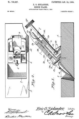
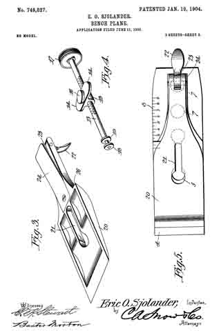
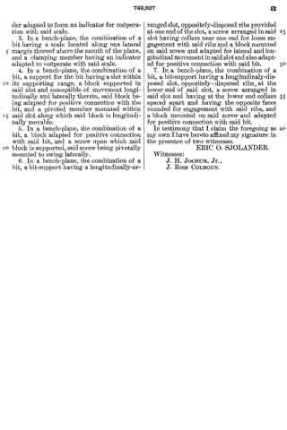
In the drawings, Figure 1 is a view in vertical longitudinal section through the plane. Fig. 2 is a view of the plane-stock and bit-support. Fig. 3 is a view in perspective of the bit-clamping plate, showing the recessed back. Fig. 4 is a perspective view of the adjusting screw and block. Fig. 5 is a plan view of the bit and the bit-clamping plate, showing the clamping-plate adjusted in position by means of the scale on the bit.

Referring to the drawings in detail, 1 designates the plane-stock, which may be of wood or metal and of any of the ordinary forms. The stock is provided with the usual opening 2 for the passage of the bit, and on the upper surface of the stock, at the rear margin of the opening 2, is provided a supporting structure 3, the forward surface of which forms a continuation of the rear wall of the opening 2. The bit 4 consists, preferably, of a single plate of steel provided at its lower end with a cutting edge and having at 5 a slot with enlarged and rounded ends for the passage of the head of a screw 6, mounted in the lower end of the supporting structure. The width of the slot 5 between the rounded end portions is of such width as just to permit of the passage of the shank of the screw 6, which is designed to serve as a fulcrum, upon which the bit 4 may be swung laterally. The bit is provided near the butt with round openings 7, for purposes that will presently appear, and along one lateral margin of the bit is formed a scale 8, for use in connection with an indicator formed on the bit-clamping plate.

The supporting structure 3 is vertically slotted at 9 from the upper end almost to the base, and at the lower end of the slot 9, which tapers slightly toward the bottom, are provided a pair of oppositely-disposed ribs 10, which lie in a plane substantially at right angles with the front surface of the support. At either side of the slot 9 is an arm 11, on the forward surface of each of which is formed a shallow recess 12 to form a way for the movement laterally and transversely of the support of one of the wings 14 of a block: 13, which is carried on the screw 15, which is supported in the slot 9 in a manner presently to be explained.

The body portion of the block 13 is sufliciently narrow to be susceptible of considerable lateral movement in the slot 9, and the wings 14 are of such proportions that they will have a similar degree of lateral movement in the recesses 12. On the forward surface of the block 13, which lies substantially flush with the forward surface of the supporting structure 3, is provided a stud 16, which is adapted for engagement with either of the round openings 7 in the plane-bit. When the parts of the plane are assembled, the stud 16 will always be brought into engagement with one of the openings 7, and when the parts are so connected the movements of the block 13 will be communicated to the bit, and conseqently any shifting of the block 13 will change the position of the bit correspondingly.

The screw 15, upon which the block 13 is carried, is provided at its upper end with a head 17 of suitable form to facilitate the rotation of the screw, and at the lower end the screw has a reduced portion which is not threaded. At the extremity of the reduced portion a collar 18 is rigidly attached, and loose upon the reduced portion between the collar 18 and the threaded portion of the screw is a second collar 19. The opposite faces of both collars 18 and 19 are rounded, as best seen in Fig. 1, and when the collars are spread apart sufficient space is provided between them to permit the passage of the ribs 10, which are spaced apart sufficiently to allow the reduced portion of the screw to be introduced between them. The rounded faces of the collars 18 and 19 permit the screw 15 to be shifted laterally with the reduced portion between the ribs 10 as a pivotal point.

In order to clamp the bit 4 rigidly in proper relation to the stock 1, I provide a bit-clamping plate 20 of the form generally used, which is provided about midway of its length with a slot 21, having the lower end thereof enlarged and rounded to permit the passage of the head of the screw 6. At the upper end of the bit-clamping plate a cam-lever 22 is pivotally mounted in a slot 23 in the clamping-plate, and on the rear surface of the clamping-plate, which is preferably recessed, as shown in Fig. 3, there is provided near the upper end of the plate a tongue 24, of thin metal, which is rigidly attached at its lower end to the clamping-plate and has the upper end thereof, which is free, disposed under the cam on lever 22. The tongue 24 is provided to prevent the contact of the cam with the bit 4, as the contact of the cam with the bit would tend to throw the bit out of adjusted position.

On the side of the clamping-plate 20 which corresponds in position to the scale 8 on the bit there is formed a shoulder 26, which is adapted to serve as an indicator in connection with said scale and to show by the coincidence of the shoulder with one of the divisions of the scale when the clamping-plate has been brought into proper relation to the bit.

In assembling the parts of the plane for use the mode of procedure is as follows: The clamping-plate 20 and the bit 4 will first be brought into proper relation, as shown in Fig. 5, and the division of the scale with which the shoulder on the clamping-plate coincides will be noted. The bit will then be introduced into the opening in the stock, and the stud 16 on the block 13 will be brought into engagement with one of the openings 7 in the bit. If the bit is new and unworn, the lower opening will be employed, and if the bit is old and much worn the upper opening will be used. The bit having been operatively connected with the block 13, the screw 15 will be rotated by means of the head 17 on the end thereof until the edge of the plane-bit has been protruded beyond the face of the stock to the distance required for the proper depth of cut. Then the screw 15 will be swung laterally, if necessary, to bring the edge of the bit into perfect parallelism with the face of the stock. During the adjustment the operator will hold the plane in such position that the relation of the edge of the bit with the face of the stock may be accurately observed. When the bit has been properly adjusted, the clamping-plate 20 will be placed in position on the forward surface of the bit, with the screw 6 extending through the opening 21 in the plate. The clamping-plate will then be brought into exact position in relation to the bit by causing the shoulder 25 to coincide with the division of the scale 8, previously noted, and the cam-lever 22 will then be operated to secure the clamping-plate in adjusted position.

From the foregoing description of the construction and mode of adjustment of the plane it will be seen that the adjustment of the bit in relation to the plane-stock is effected independently of the adjustment of the clamping-plate and that the relative positions of the clamping-plate and bit to produce the desired result having been noted at the beginning of the operation of adjustment of parts of the plane the clamping-plate may be brought at once into proper relation to the bit and secured without deranging the adjustment of the bit in relation to the stock. It will also have been observed that by providing a scale on the bit and an indicator of a suitable form on the clamping-plate a degree of accuracy of adjustment of the clamping-plate and bit may be secured, which is impossible in planes not so constructed.

A special advantage inherent in the construction hereinbefore described is in the mode of supporting the screw 15 and the adjusting-block 13, by which it is made possible to effect the adjustment of the plane-bit as to depth of out and as to parallelism with the face of the stock by a single adjusting means.

Having thus described the construction and operation of my invention, what I claim as new, and desire to secure by Letters Patent, is —

1. In a bench-plane, the combination of a bit bearing a scale located above the mouth of the plane, and a bit-clamping member having an indicator adapted to cooperate with said scale.

2. In a bench-plane, the combination of a bit bearing a scale above the mouth of the plane, and a clamping member having a shoulder adapted to form an indicator for cooperation with said scale.

3. In a bench-plane, the combination of a bit having a scale located along one lateral margin thereof above the mouth of the plane, and a clamping member having an indicator adapted to cooperate with said scale.

4. In a bench-plane, the combination of a bit, a support for the bit having a slot within its supporting range, a block supported in said slot and susceptible of movement longitudinally and laterally therein, said block being adapted for positive connection with the bit, and a pivoted member mounted within said slot along which said block is longitudinally movable.

5. In a bench-plane, the combination of a bit, a block adapted for positive connection with said bit, and a screw upon which said block is supported, said screw being pivotally mounted to swing laterally.

6. In a bench-plane, the combination of a bit, a bit-support having a longitudinally-arranged slot, oppositely-disposed ribs provided at one end of the slot, a screw arranged in said slot having collars near one end for loose engagement with said ribs and a block mounted on said screw and adapted for lateral and longitudinal movement in said slot and also adapted for positive connection with said bit.

7. In a bench-plane, the combination of a bit, a bit-support having a longitudinaly-disposed slot, oppositely-disposed ribs, at the lower end of said slot, a screw arranged in said slot and having at the lower end collars spaced apart and having the opposite faces rounded for engagement with said ribs, and a block mounted on said screw and adapted for positive connection with said bit.

In testimony that I claim the foregoing as my own I have hereto affixed my signature in the presence of two witnesses.

ERIC O. SJOLANDER.

Witnesses:
J. H. JOCHUM, Jr.,
J. ROSS COLHOUN.

No. 748,199 – Matching-Plane (Alexander Mason) (1903)

[paiddownloads id=”595″]748199


UNITED STATES PATENT OFFICE.

_________________

ALEXANDER MASON, OF SALEM, MASSACHUSETTS.

MATCHING-PLANE.

_________________

SPECIFICATION forming part of Letters Patent No. 748,199, dated December 29, 1903.
Application filed March 20, 1903. Serial No. 148,745. (No model.)

_________________

To all whom it may concern:

Be it known that I, ALEXANDER MASON, a citizen of the United States, residing at Salem, in the county of Essex and State of Massachusetts, have invented certain new and useful Improvements in Matching-Planes; and I do hereby declare the following to be a full, clear, and exact description of the invention, such as will enable others skilled in the art to which it appertains to make and use the same.

This invention relates to matching-planes; and it consists in the novel construction and combination of the parts hereinafter fully described and claimed.

In the drawings, Figure 1 is a side view of the matching-plane. Fig. 2 is a cross-section taken on the line x x in Fig. 1. Fig. 3 is a partial plan view showing the clamping-levers and looking in the direction of the arrow y in Fig. 1.

A is the body of the plane, provided with a handle B at one end and a knob C at the other end. The body portion A has a broad groove b and a narrow groove c in its under side, and D is a longitudinal rib on the upper side of the body portion.

E is an inclined support for the blades, which also projects on the upper side of the body portion, and d represents slots or notches in the body portion A for the blades to project through.

F is a single cutting-blade, and G is a forked cutting-blade. These blades are laid upon the support E, one on each side of the rib D, and are clamped in position by means of two clamping-levers f and g, which are pivoted on the end portions of a pin H, which is secured in the rib D. These clamping-levers are provided at their upper ends with thumb-screws f’ and g’, which bear against the blades, so that the lower ends of the levers clamp the said blades securely in position.

I is a guide for the plane. This guide is provided with projecting brackets i at its end and middle portions. The end brackets carry bars J, which are slidable in guide-holes j in the body of the plane. The middle bracket carries a bar K, which is slidable in a hole k in the body of the plane and which is provided with a series of cross-holes m.

M is a spring-pressed stop-pin which is slidable in a lug n on the body of the plane and which engages with the said cross-holes. The guide is slid so as to suit the work, and it is then secured in position by means of the said stop-pin.

The two blades form three separate cutters, and they will tongue and groove boards of widely-varying thickness in a very satisfactory manner.

What I claim is —

In a matching-plane, the combination, with a body portion, of a guide for the said body portion provided with projecting brackets at its middle and end portions, bars projecting from the said end brackets and slidable in cross-holes in the said body portion, a bar projecting from the middle bracket and provided with a series of cross-holes and slidable in a hole in the said body portion, and a spring-actuated stop-pin carried by the said body portion and engaging with the cross-holes of the said bar.

In testimony whereof I affix my signature in presence of two witnesses.

ALEXANDER MASON.

Witnesses:
ALICE J. MURRAY,
FRED. K. DAGGETT.

No. 746,286 – Plane-Iron (John W. Carleton) (1903)

[paiddownloads id=”594″]746286


UNITED STATES PATENT OFFICE.

_________________

JOHN W. CARLETON, OF NEW BRITAIN, CONNECTICUT, ASSIGNOR TO
UNION MANUFACTURING COMPANY, OF NEW BRITAIN, CONNECTICUT,
A CORPORATION OF CONNECTICUT.

PLANE-IRON.

_________________

SPECIFICATION forming part of Letters Patent No. 746,286, dated December 8, 1903.
Application filed September 19, 1903. Serial No. 173,821. (No model.)

_________________

To all whom it may concern:

Be it known that I, JOHN W. CARLETON, a citizen of the United States, residing at New Britain, in the county of Hartford and State of Connecticut, have invented certain new useful Improvements in Plane-Irons, of which the following is a specification.

My invention relates to improvements in plane irons or cutters; and the object of my improvement is to facilitate securing the bit-adjusting bolt to the body of the cutting-bit or plane-iron.

In the accompanying drawings, Figure 1 is a plan view of my plane-iron. Fig. 2 is a side elevation of the same. Fig. 3 is a reverse plan view of the same. Fig. 4 is a detached side elevation of the adjusting-bolt with the nut removed. Fig. 5 is a plan view of the same.

A designates the cutting-bit, having the usual longitudinal slot 6, within the lower end of which is the bolt 7, by which to connect the said cutting-bit with any ordinary devices for adjusting the said bit longitudinally. This bolt has its head 8 projecting from the under side of the bit and is provided with a slot 9 to receive a projection of the lever or other device for adjusting the bit longitudinally. A portion of the head is slabbed off on opposite sides, as at 10, Figs. 4: and 5, to let the said bolt-head into the slot 6 of the bit, with the said slabbed-off portions acting in connection with the sides of the slot to prevent the said bolt from rotating within the said slot. The end or body of the bolt 7 is screw-threaded and receives a nut 11, which rests upon smooth surfaces on the upper broad side of the cutting-bit or plane-iron and by which nut the said bolt may be adjustably secured at any desired position in the lower end of the said slot. This nut is provided with a screw-driver slot 12 to facilitate securing it in place. As shown, the periphery of the said nut is also provided with a knurled surface to facilitate turning the nut with one’s fingers.

Upon each side of the slot 6, from its lower end upwardly a part of the length of the said slot, there is formed a roughened face 13, Fig. 3, which may be simply a series of alternate fine grooves and ridges extending from the edges of the slot 6 outwardly about the same distance that the bolt-head 8 projects beyond the said edges. These roughened surfaces come under the non-rotating head of the bolt, which is drawn firmly against them by tightening up the nut. This nut bears on smooth surfaces, so that it turns smoothly when it is rotated to draw the bolt-head against the roughened surfaces on the opposite broad side of the cutting-bit, whereby the bolt can be readily and firmly secured in its adjusted position without applying excessive power to the nut. This bolt is designed to be set in the proper position to connect with the longitudinally-adjusting devices when the lower end of the cutting-bit is within its proper range of movement relatively to the throat of the plane-stock. When the cutting-bit is shortened up by wear and repeated grinding, so as not to have the proper range of movement relatively to the throat, the bolt can be readjusted accordingly.

I claim as my invention —

The herein-described cutting-bit having the central longitudinal slot with adjacent smooth surfaces on one broad side of the said bit, and roughened surfaces adjacent to the said slot on the opposite broad side of the said bit and the non-rotating bolt fitted to the said slot and provided with means for being connected with the longitudinally-adjusting devices for the said bit, the said bolt being arranged in the said slot with its head bearing on the said roughened surfaces on one broad side of the said bit and the nut bearing on the opposite broad side of the said bit.

JOHN W. CARLETON.

Witnesses:
JAMES SHEPARD,
SHEFFIELD H. CLARKE.

No. 746,285 – Plane (John W. Carleton And George E. Trask) (1903)

[paiddownloads id=”593″]746285


UNITED STATES PATENT OFFICE.

_________________

JOHN W. CARLETON AND GEORGE E. TRASK, OF NEW BRITAIN, CONNECTICUT,
ASSIGNORS TO THE UNION MANUFACTURING COMPANY, OF NEW BRITAIN, CONNECTICUT.

PLANE.

_________________

SPECIFICATION forming part of Letters Patent No. 746,285, dated December 8, 1903.
Application filed August 1, 1903. Serial No. 167,897. (No model.)

_________________

To all whom it may concern:

Be it known that we, JOHN W. CARLETON and GEORGE E. TRASK, citizens of the United States, residing at New Britain, in the county of Hartford and State of Connecticut, have invented certain new and useful Improvements in Planes, of which the following is a specification.

Our invention relates to improvements in planes; and the objects of our improvement are simplicity and economy in construction and convenience and efficiency in operation.

In the accompanying drawings, Figure 1 is side elevation of our plane. Fig. 2 is a central longitudinal section of the same, partly in elevation. Fig. 3 is a plan view of the same with the holding-cap, cap-iron, and cutting-bit removed. Fig. 4 is a side elevation of the middle portion of the iron frame of the stock. Fig. 5 is a side elevation of our plane when made with an iron stock without the wooden body. Fig. 6 is a sectional view of the same on the line x x of Fig. 5 when viewed in the direction of the dart in the said Fig. 5, the cutter being removed. Fig. 7 is a sectional side elevation of the middle portion of the stock and the adjusting-levers. Figs. 8 and 9 are plan and reverse plan views, respectively, of the cutting-bit with attached cap-iron and adjusting-nut, the same being adapted for use in both of the constructions herein shown. Fig. 10 is a plan view of the holding-cap and its screw.

A designates the wooden body, and B the iron frame, the said two parts together forming the stock of the plane. If desired, the wooden body A of the stock may be provided with a metal sole 5; but this is not essential. The frame B has an end plate 6 at its forward end provided with a hole for receiving the holding-screw 7 and also with a seat for the knob 8, the said seat being centrally perforated to receive the screw 9, that serves the double function of securing the said knob in place and of assisting to secure the said frame to the wooden body of the stock. At the rear end of the plate 6 there is a cross-rib 10, and extending rearwardly from the ends of the said cross-rib at opposite sides of the stock are the two side pieces 11 of the iron frame B, with the holding-lugs 12 on their confronting inner faces over the opening for the throat 13 of the stock. These side pieces 11 extend parallel to each other along the sides of the stock to a point in the rear of the middle of the length of the stock and then turn inwardly toward each other to the handle-seat 14 on the rear plate 15, near the end of which is the hole for the holding-screw 16. An ordinary handle 22 is secured to the handle-seat 14 by the rod 17, which is screw-threaded at its ends, one end being screwed into the threaded boss 18 on said handle-seat, while the other end is provided with the holding-nut 19.

The rear plate 15 extends forwardly to the side wings 20 of the frog, into which the said plate merges. An opening 21 is left in the rear plate between the said side wings 20 and rearwardly thereof. to near the handle 22. The side wings 20 of the frog are connected together near their upper ends by a bridge 23. The inclined front faces of the two side wings of the frog and the adjacent part of the rear plate form a seat for the cutting-bit in continuation of the inclined rear wall 24 of the throat of the stock. The side wings 20 of the frog are formed with a lug 25, Fig. 4, that extends below the base of the frame side pieces 11, and between these lugs we pivot a hub 26, having a short lever-arm 27 for engaging a slot in some device connected with the cutting-bit 28 or its cap-iron 29. The said hub is also provided with a longer lever-arm 33, that extends rearwardly from the hub for use as a handle in operating the said short lever-arm and cutting-bit for its endwise adjustment. Such levers of themselves, broadly speaking, are not of our invention. As shown, the short arm 27 of the lever engages a slot 36, Fig. 9, in the head of the screw 30, Fig. 2, which is held in the ordinary longitudinal slot of the cutting-bit 28 by means of the nut 31, the head of the said screw being shouldered by slabbing off on each side, as at 32, Fig. 2, so that the slabbed-off portion of the screw-head may enter the slot in the bit. On the upper face of the bridge 23 we pivot an ordinary laterally-adjusting lever 34. We secure the cutting-bit in place by means of a holding-cap C, the lower end of which is inserted under the confronting holding-lugs 12, after which the parts are tightened by turning in the holding-screw 35 at the upper end of the holding-cap C.

The stock Ba as shown in Figs. 5, 6, and 7, is wholly of iron and quite closely resembles the iron frame B, before described, only it is not adapted to have a wooden body secured thereto, and consequently its side pieces 11a are extended parallel to each other for nearly the whole length of the stock. These side pieces have on their inner faces the holding-lugs 12, before described. The side wings 20a of the frog are substantially the same as before described, only they are proportionally longer as the height of the inclined rear wall 24a of the throat 13 in the iron stock is less than in the wooden body of the stock first described. Like the side wings first described, a bridge 23 is provided to connect their upper ends. While there is an open space between the side wings 20a for pivoting the hub 26 of the lever 27 33, the pivot of the said lever comes higher up on the wings, and the lugs, which in the first-described construction project downwardly below the base of the wings, are omitted. The pivot-pin 37 for the hub 26 may for convenience of heading it pass through the side pieces 11a as well as the wings 20a The cutting-bit and connected parts and both of the adjusting-levers are the same as first described and have the same reference-numerals.

We claim as our invention —

1. In a plane, the frame of the stock having the side pieces 11, a frog between the said side pieces having the side wings with open space between, and the bridge 23 connecting the upper corners of the said side wings, which bridge forms a support for the laterally-adjusting lever.

2. In a plane, the stock having the side pieces, a frog between the said side pieces having the side wings with open space between, a bridge connecting the upper ends of the said side wings and forming a support for a laterally-adjusting lever, and an adjusting-lever consisting of a hub, short arm and longer operating-arm, the same being pivoted in the open space between the lower part of the said side wings and in front of the said bridge, with the body of said operating-arm working between the said wings while its handle end extends under the said bridge beyond the said wings at the rear thereof.

3. The herein-described plane, comprising the wooden body and iron frame of the stock, the said frame having the front and rear plates, connecting side pieces, and the frog between the said side pieces having the side wings with open space between and bridge at their upper corners forming a support for the laterally-adjusting lever.

4. The herein-described plane, comprising the wooden body and iron frame of the stock, the said frame having the front and rear plates with knob and handle seats, side pieces connecting the said plates and the frog between the said side pieces, the said frog having the side wings with open space between, the inclined front faces of the said side wings and the adjacent part of the said rear plate forming a direct seat for the cutting-bit, while the lower parts of the said side wings form a support for the longitudinaliy-adjusting lever.

5. The herein-described plane, comprising a wooden body and frame of the stock, the said frame having front and rear plates, connecting side pieces with the confronting holding-lugs on their inner faces, a frog between the said side pieces having the side wings with open space between, a bridge at the upper corners of the said wings forming a support for a laterally-adjusting lever, and lugs at the lower corners of the said wings for the longitudinally-adjusting lever.

6. In a plane, the stock having side pieces, a frog between the said side pieces composed mainly of a pair of inclined side wings with open space between, and aconnecting-bridge 23, at the upper ends of the said side wings that spans the said open space between them, the said side pieces forming a support for the longitudinally-adjusting lever and the said bridge forming a support for the laterally-adjusting lever, substantially as described.

7. In a plane, the stock having side pieces, a frog between the side pieces having the side wings with open space between, a longitudinally-adjusting lever with its long and short arms pivoted between the said side wings with the upper end of the said long arm projecting rearwardly from the space between the said side wings, a bridge connecting the upper ends of the said side wings, and a laterally-adjusting lever pivoted on the said bridge.

JOHN W. CARLETON.
GEORGE E. TRASK.

Witnesses:
JAMES SHEPARD,
SHEFFIELD H. CLARKE.