
| PLEASE NOTE: The images presented on this page are of low resolution and, as a result, will not print out very well. If you wish to have higher resolution files then you may purchase them for only $2.95 per patent by using the "Buy Now" button below. All purchases are via PayPal. These files have all been cleaned up and digitally enhanced and are therefore suitable for printing, publication or framing. Each zip package contains all the images below (some packages may contain more), and purchased files can be downloaded immediately. |
UNITED STATES PATENT OFFICE.
_________________
JACOB SIEGLEY, OF WILKES-BARRE, PENNSYLVANIA, ASSIGNOR TO STANLEY RULE & LEVEL COMPANY, OF NEW BRITAIN, CONNECTICUT, A CORPORATION OF CONNECTICUT.
PLANE.
_________________
1,032,956. Specification of Letters Patent. Patented July 16, 1912.
Application filed October 18, 1911. Serial No. 655,361.
_________________
To all whom it may concern:
Be it known that I, JACOB SIEGLEY. a citizen of the United States, residing at Wilkes-Barre, Luzerne county, Pennsylvania, have invented certain new and useful Improvements in Planes, of which the following is a full, clear, and exact description.
My invention relates to planes, particularly of the kind known as router or beading planes, which are adapted for beading, matching or rabbeting.
The object of the invention is to provide an improved construction in which the mouth of the planemay be easily freed of shavings; to provide an improved depth gage between the runners to determine the depth of a matched tongue or beading ; to provide improved means for steadying the parts of the adjustable runner, and to improve the structure of these planes generally.
With these objects in view, the invention consists in the construction and arrangment of parts, the preferred embodiment of which is illustrated in the accompanying drawings, in which —
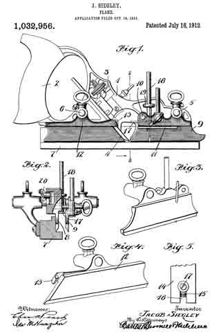
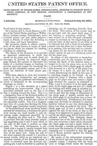
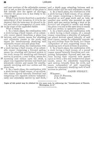
Figure 1 is a side elevation of a plane embodying my improvements. Fig. 2 is a transverse sectional view on the the line 2–2 Fig. 1, looking toward the front. Fig. 3 is a perspective view of the forward section of the adjustable runner detatched. Fig. 4 is a view similar to Fig. 3 of the rear section of the adjustable runner. Fig. 5 is a fragmentary view of a plane iron showing the form of depth gage heretofore usually employed.
In the embodiment of my invention herein selected for illustration, 1 indicates the plane stock having the usual handle 2, and adjusting means designated generally by 3 for adjusting the plane iron 4. The stock is provided with the usual laterally extending supporting pins 5 and 6 upon which at one side of the stock is secured an edge guide 7. The stock, furthermore, is provided with a runner 8, usually integral with the stock and fixed relatively to the position of the plane iron. Upon the side of the stock opposite the runner 8 I provide a second runner, which in my improved construction consists of the forward section 9, which is mounted upon the forward supporting pin 5 and is steadied in position by steadying pin 10 extending laterally from the stock. This section of the runner may be provided with the usual depth gage 11 for beading or matching purposes. The rear section 12 of this two-part adjustable runner is mounted on the supporting pin 6, and the body of this section is provided at its forward end with a hook 13 arranged to extend over the plane iron 4 when the latter is in position, thus serving both as a steadying means for the forward end of the rear runner section 12 and as a steadying means for the plane iron.
In planes of this character as heretofore constructed, and for the purposes of determining the depth of the channel, bead or tongue to be cut, the plane iron, as 14, Fig. 5, is provided with a depth gage 15, adjustably mounted in a slot 16 of the plane iron by means of a screw 17, said slot 16 of course determining the depth in this case of a matching tongue to be formed. In my improved plane I dispense with a depth gage on the plane iron and mount a depth gage between the runners, as indicated in Figs. 1 and 2, in which 17 is the depth gage shoe, 18 the depth gage rod and 19 a clamp for holding said depth gage in adjusted position. By an inspection of Figs. 1 and 2 it will be seen that the range of adjustment of the depth gage 17 greatly exceeds that of the depth gage 15 on the plane iron as heretofore constructed. Furthermore, this depth gage may obviously be adjusted to required position without in any way disturbing the plane iron then mounted in the stock. The depth gage rod 18 has a suitable bearing against the side of the stock, so that as the clamp 19 is tightened by means of its thumb nut 20, the depth gage will be firmly held in adjusted position. This clamping means constitutes one of the features of my invention and comprises a head which surrounds the depth gage rod and a shank which extends through a suitable perforation in the stock upon the extremity of which shank the clamping nut is mounted so that the gage rod is drawn securely against the bearing face on the stock.
By reason of the independent mounting of the forward and rear sections of the adjustable runner, I dispense with the usual arch or bridge which unites the forward and rear portions of the adjustable runners now in use, so that the mouth of the plane is left entirely free for egress of shavings, whereby the plane iron is less likely to become clogged.
While I have herein described a particular embodiment of my invention, it is to be understood that the same may be altered in detail and relative arrangement of parts within the scope of the appended claims.
What I claim is:
1. In a bench plane, the combination with a stock having a fixed runner, of an adjustable runner spaced therefrom, a plane iron between said runners, means for attaching said adjustable runner to the stock, and means for simultaneously steadying said adjustable runner and said plane iron.
2. In a bench plane, the combination with a stock having a fixed runner, of an adjustable runner comprising a forward section, means for attaching said forward section to the stock, means for steadying said forward section in position, a rear section, means for mounting said section upon the stock, a plane iron supported between said fixed and adjustable runners and means for simultaneously steadying said rear section and the plane iron.
3. In a bench plane, the combination with a stock having a fixed runner, of an adjustable runner spaced laterally therefrom and comprising two separate sections independently and adjustably carried by said stock, and a depth gage extending between said fixed runner and the said adjustable runner.
4. In a bench plane, the combination with a stock having a fixed runner, of an adjustable runner comprising a forward section mounted on said gage stock and an independent rear section also mounted on said stock, said rear section having a hook at its forward end adapted to overlie and steady the plane iron at the same time to steady said rear section in operative position.
5. In a bench plane, the combination with a stock having a fixed runner, of a second runner comprising a plurality of independent aligned sections spaced laterally of said fixed runner, means for adjustably supporting said sections from the stock, and means independent of said supporting means for steadying each of said sections in position.
6. In a bench plane, the combination with a stock having a fixed runner, of a second runner spaced laterally therefrom and comprising independent forward and rear sections having their adjacent ends spaced apart to form a free and unobstructed plane mouth, means for adjustably supporting said sections laterally from the stock, and means independent of said supporting means for separately steadying each of said sections in position.
JACOB SIEGLEY.
Witnesses:
JOHN P. POLLOCK,
J.L. CAREY.
_________________
Copies of this patent may be obtained for five cents each, by addressing the “Commissioner of Patents, Washington, D. C.”
_________________