
| PLEASE NOTE: The images presented on this page are of low resolution and, as a result, will not print out very well. If you wish to have higher resolution files then you may purchase them for only $2.95 per patent by using the "Buy Now" button below. All purchases are via PayPal. These files have all been cleaned up and digitally enhanced and are therefore suitable for printing, publication or framing. Each zip package contains all the images below (some packages may contain more), and purchased files can be downloaded immediately. |
UNITED STATES PATENT OFFICE.
_________________
ALBERT A. PAGE, OF NEW HAVEN, CONNECTICUT, ASSIGNOR TO SARGENT & COMPANY,
OF NEW HAVEN, CONNECTICUT, A CORPORATION OF CONNECTICUT.
TONGUE-AND-GROOVE PLANE.
_________________
1,042,139. Specification of Letters Patent. Patented Oct. 22, 1912.
Application filed September 23, 1911. Serial No. 650,904.
_________________
To all whom it may concern:
Be it known that I, ALBERT A. PAGE, a citizen of the United States, residing in the city and county of New Haven, State of Connecticut, have invented new and useful Improvements in Tongue-and-Groove Planes, of which the following is a full, clear, and exact description when taken in connection with the accompanying drawings.
My invention relates to reversible or invertible tongue and groove planes, and the primary object of the invention is to provide a tool of this sort which is practically as handy and convenient in use as the well known tongue cutting planes and grooving planes in which the tongue cutting function and the groove cutting function are not combined.
It is also aimed to produce a plane of this kind which is not only handy and well balanced but also of comparatively light, simple and inexpensive construction. The main advantage of the improved tool resides, however, in the fact that it provides a very convenient and satisfactory grip for the workman, whether used for tongue cutting or grooving, and that it is peculiarly compact, and has the respective cutters so arranged as to do the most effective work.
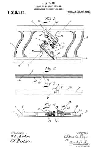
In these drawings, Figure 1 is a side elevation of the plane; Fig. 2, a plan view of the edge adapted to fit the groove; Fig. 3, a plan view of the edge adapted to form and engage the tongue; and Fig. 4, a cross section on the line x–x of Fig. 1.
In all figures, similar letters of reference represent like parts.
Referring to the drawing, the open skeleton frame constituting the stock is shown at 1. This frame comprises parallel lower and upper edge portions 4, 5, of which the former acts as a bearing surface when cutting the tongue, while the latter serves as a bearing surface in cutting the groove. These parallel bearing portions of the skeleton frame are connected at the ends of the plane, preferably in an integral manner, by handle or grip portions 2, 3, respectively. These handle or grip portions, while slightly curved in a longitudinal direction and of appropriate cross-section, in order to form a convenient and satisfactory grip for the hand of the workman, are generally parallel with respect to each other and form, in connection with the parallel bearing portions, 4, 5, a stock of substantially rhomboidal shape.
Projecting inwardly from the respective bearing portions 4, 5, are lugs or brackets 13 and 15 respectively against which the respective bits 8 and 14: are positioned. The supporting brackets or lugs 13 and 15 are preferably formed integrally with the bearing portions 4 and 5 and are equipped with flat bearing surfaces for the bits, which bearing surfaces are directed parallel to each other and substantially parallel with one of the diagonals of the rhomboidal figure formed by the intermediate open space between the handles 2 and 3. By placing the supporting brackets and the bits in superposed relation, as shown, with one bracket and its bit placed oppositely with respect to the other bracket and bit as regards the diagonal aforesaid, it is possible to shorten the plane materially while still providing for the location of the cutting edges of the respective bits at the proper distances from the respective ends of the plane. In other words, by this construction I am enabled to provide an efficient plane of minimum length wherein the distance from each cutter to one end of the plane bears such a ratio to the distance from said cutter to the other end of the plane that the bearing portions 4, 5, coact properly and effectively with the respective bits.
The bearing portion 4 is provided at one side with a relatively short depending flange 6 creating a groove 7 into which projects the tongue cutting bit 8, the cutting end of which is recessed at 9 in order to form the tongue in well known manner. The bit 8 is positioned relatively to its support 13 by means of a lever pivoted at 12 and bearing against the bit at one end, while the opposite end carries a clamping screw 10 coacting with the bit in well known manner. The bearing portion 5 is provided with a groove 20 and with a flange 19 alined with the cutting edge 21 of the bit or cutter 14. This bit or cutter is positioned relatively to its support 15 by means of a lever 16 pivoted at 17 and having a clamping screw 18.
The operation of the device is as follows: When it is employed for forming and planing the tongue in the edge of the work, the latter is engaged with the groove 7 and the grip member 2 engaged by the hand of the operator. In the operation of the device in this position the slot 9 will leave a central unplaned space on the edge of the board of the desired width of the tongue and in the continued movement of the plane the portions on either side of this space will be planed down so as to form a tongue of the proper width. After the tongue has been formed it is merely necessary to reverse the plane edge for edge and grasp the grip member 3 by the hand and apply the rib 19 to the opposite edge of the board or edge of another board, and then operate the plane for the purpose of forming the groove, the cutter 21 engaging said edge and forming the groove.
By forming the plane of substantially rhomboidal shape a most satisfactory grip may be afforded by the handles 2 and 3. By locating the bits and bit supports in the manner described the construction of the tool is simplified and its expense lowered, and in addition to this, the tool is made light and well balanced, and is especially effective in operation.
Having thus described my invention, what I claim and desire to secure by Letters Patent, is :–
l. An invertible or reversible tongue and groove plane comprising parallel oppositely located bearing portions, handle members joining the respective ends of the respective bearing portions and forming in conjunction with said bearing portions a skeleton frame or stock of substantially rhomboidal form, separate bit supports projecting from the respective bearing portions into the inner open portion of the frame or stock, said bit supports being arranged in superposed relation and having bearing surfaces directed substantially parallel to one of the diagonals of the rhomboidal opening of the frame or stock, and bits clamped on the respective bearing surfaces and cooperating with the respective bearing portions; substantially as described.
2. An invertible or reversible tongue and groove plane comprising parallel oppositely located bearing portions, handle members joining the respective ends of said bearing portions and forming in conjunction therewith a skeleton frame or stock of approximately rhomboidal form, bit supports formed integrally with the respective bearing portions and extending therefrom into the inner open portion of the frame or stock, and bits clamped on the respective bit supports, substantially as described.
3. ln an invertible or reversible tongue and groove plane, an open skeleton frame formed of oppositely arranged parallel bear-
ing portions and handle members connecting the respective bearing portions at the ends of the plane, approximately parallel bit supports extending inward from the respective bearing portions into the inner opening of the frame, said bit supports being arranged in superposed relation and having their bit supporting surfaces opposing or facing each other, and bits clamped on said surfaces and cooperating with the respective bearing portions, substantially as described.
ln witness whereof, I have hereunto set my hand on the 21st day of September, 1911.
ALBERT A. PAGE.
Witnesses:
HENRY H. MUNSON,
CARL W. CARLSON.
Copies of this patent may be obtained for five cents each, by addressing the “Commissioner of Patents, Washington, D. C.”
_________________