
| PLEASE NOTE: The images presented on this page are of low resolution and, as a result, will not print out very well. If you wish to have higher resolution files then you may purchase them for only $2.95 per patent by using the "Buy Now" button below. All purchases are via PayPal. These files have all been cleaned up and digitally enhanced and are therefore suitable for printing, publication or framing. Each zip package contains all the images below (some packages may contain more), and purchased files can be downloaded immediately. |
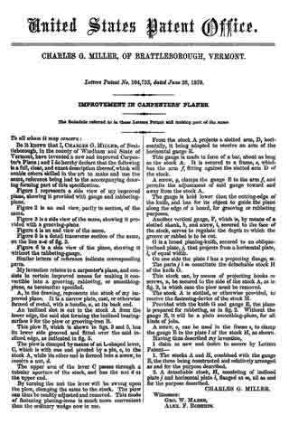
United States Patent Office.
CHARLES G. MILLER, OF BRATTLEBOROUGH, VERMONT.
Letters Patent No. 104,753, dated June 28, 1870.
_________________
IMPROVEMENT IN CARPENTERS’ PLANES.
_________________
The Schedule referred to in these Letters Patent and making part of the same.
_________________
To all whom it may concern:
Be it known that I, CHARLES G. MILLER, of Brattleborough, in the county of Windham and State of Vermont, have invented a new and improved Carpenter’s Plane; and I do hereby declare that the following is a full, clear, and exact description thereof, which will enable others skilled in the art to make and use the same, reference being had to the accompanying drawing forming part of this specification.
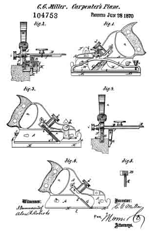
Figure 1 represents a side view of my improved plane, showing it provided with gauge and rabbeting plane.
Figure 2 ls an end view, partly in section, of the same.
Figure 3 is a side view ofthe same, showing it provided with a grooving-plane.
Figure 4 is an end view of the same.
Figure 5 is s. detail transverse section of the same, on the line x x of fig. 3.
Figure 6 is a side view of the plane, showing it without the rabbeting-gauge.
Similar letters of reference indicate corresponding parts.
My invention relates to a oarpenter’s plane, and consists in certain improved means for making it convertible into a grooving, rabbetlng, or smoothing-plane, as hereinafter specified.
A, in the drawing, represents the stock of my improved plane. It is a narrow plate, cast, or otherwise formed of metal, with a handle, a, at its back end.
An inclined slot is cut in the stock A from the lower edge, the said slot forming the inclined bearing-surface b for the plow or grooving-iron B.
This plow B, which is shown in figs. 3 and 5, has its lower side grooved and fitted over the said inclined edge, as indicated in fig. 5.
The plow is clamped by means of an L-shaped lever, C, which is with one end pivoted by a pin, c, to the stock A, while its other end is formed into a screw, to receive a nut, d.
The upper arm of the lever C passes through. it tubular aperture of the stock, and has the nut d at the upper end.
By turning the nut the lever will be swung upon the plow, clamping the same to the stock. The plow can thus be readily adjusted and removed. This mode of fastening planing-irons is much more convenient than the ordinary wedge now in use.
From the stock A projects a slotted arm, D, horizontally, it being adapted to receive an arm of the horizontal gauge E.
This gauge is made in form of a bar, about as long as the stock A. It is secured to a frame, e, which has the arm f fitting against the slotted arm D of the stock.
A screw, g, clamps the gauge E to the arm f and permits the adjustment of said gauge toward and away from the stock A.
The gauge is held lower than the cutting-edge of the knife, and has for its object to guide the plane along the edge of a board, for grooving or rabbeting purposes.
Another vertical gauge, F, which is, by means of a slotted shank, h, and screw, i, secured to the face of the stock, serves to regulate the depth to which the groove or rabbet is to be cut.
G is a broad planing-knife, secured to an oblique-inclined plate, j, that projects from a horizontal plate, l, of equal width.
On one side the plate l has a projecting flange, m. The parts j l m constitute the detachable stock H ofthe knife G.
This stock can, by means of projecting hooks or screws, n, be secured to the side of the stock A, as in fig. 2, in which case the plow must be removed.
The stock A is slotted, or otherwise provided, to receive the fastening-device of the stock H.
Provided with the knife G and gauge E, the plane is prepared for rabbeting, as in fig. 2. Without the gauge E, it will be a plain smoothing-plane, for all kinds of jobs.
A screw, o, can be used in the frame e, to clamp the gauge E to the plate l of the stock H, as shown.
Having thus described my invention,
I claim as new and desire to secure by Letters Patent —
1. The stocks A and H, combined with the gauge E, the three being constructed and relatively arranged as and for the purpose described.
2. A detachable stock, H, consisting of inclined plate j and horizontal plate l, flanged at m, all as and for the purpose described.
CHARLES G. MILLER.
Witnesses:
GEO. W. MABEE,
ALEX. F. ROBERTS.