
| PLEASE NOTE: The images presented on this page are of low resolution and, as a result, will not print out very well. If you wish to have higher resolution files then you may purchase them for only $2.95 per patent by using the "Buy Now" button below. All purchases are via PayPal. These files have all been cleaned up and digitally enhanced and are therefore suitable for printing, publication or framing. Each zip package contains all the images below (some packages may contain more), and purchased files can be downloaded immediately. |


UNITED STATES PATENT OFFICE.
_________________
CHRISTIAN BODMER AND JAMES M. BURDICK, OF NEW BRITAIN, CONNECTICUT, ASSIGNORS TO THE
STANLEY RULE & LEVEL COMPANY, OF NEW BRITAIN, CONNECTICUT, A CORPORATION OF CONNECTICUT.
PLANE.
_________________
1,053,270. Specification of Letters Patent. Patented Feb. 18, 1913.
Application filed July 10, 1913. Serial No. 708,733.
_________________
To all whom it may concern:
Be it known that we, CHRISTIAN BODMER and JAMES M. BURDICK, citizens of the United States, residing at New Britain, Hartford county, State of Connecticut, have invented certain new and useful Improvements in Planes, of which the following is a full, clear, and exact description.
This invention relates to planes and particularly to an improved form of “plane iron” or cutter cap.
In planes heretofore it has been customary to provide the cutters or “plane irons” with a detachable cap piece adapted to be seated thereover and provided with means for clamping the cutter in its adjusted position on its seat.
Our invention contemplates forming such a detachable cap with a plurality of relatively movable parts, one of which constitutes a palm rest, the cap being provided with means cooperating in one position of the parts to clamp the cutter in position on its seat against accidental displacement and to hold the cap against movement when in such locking position. The clamping of the cutter on its seat is such that it may be adjusted through suitable means without disturbing the position of the cap parts which will act to hold the cutter in its new position against accidental displacement.
In the specific embodiment of the invention selected for illustration, the parts easily susceptible of accidental actuation are housed within the palm rest when the cap is seated over the cutter in clamping position, and are thereby protected against accidental actuation to destroy the adjustment. In addition the positioning of the parts of the cap over the cutter to hold the same upon its seat against accidental displacement serves to retain the cap on the cutter against displacement relative thereto and to the plane, although, of course, adjustment of the cutter itself is possible as already stated. These and other advantages will be seen from the more detailed description following and from the accompanying drawings in which:
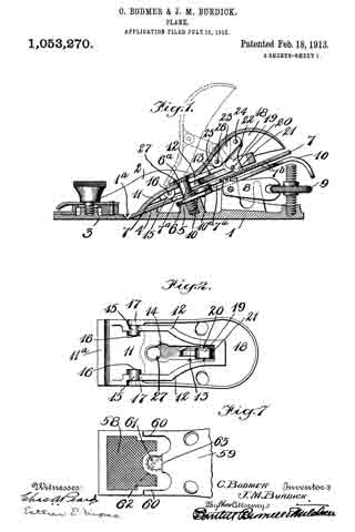
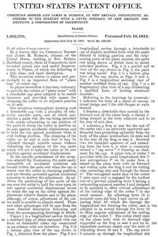
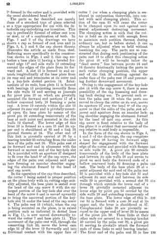
Figure 1 is a longitudinal section through a standard type of plane equipped with one form of detachable cutter cap constructed in accordance with our invention. Fig. 2 is a bottom plan view of the cap shown in Fig. 1, detached from the plane. Fig. 3 is a longitudinal section through a detachable cap of slightly modified form with the parts thereof in locking position and the cooperating parts of the plane omitted, the palm rest being shown in dotted lines in raised unlocked position. Fig. 4 is a partial end view of the cap shown in Fig. 3, the palm rest being raised. Fig. 5 is a bottom plan view of the cap shown in Figs. 3 and 4. Fig. 6 is a longitudinal sectional view of another modified form of cap. Fig. 7 is a fragmentary plan view of a cap illustrating a modified form of locking abutment shoulder.
Referring to the drawings by numerals: 1 indicates the body of a plane of conventional design and 2 the side flanges or walls thereof. 3 denotes a detachable shoe carried by the forward end of the plane body, a throat 1a being formed in the body adjacent and to the rear of said shoe.
4 indicates a frog or se-at for the end of the cutter and 5 an interiorly apertured and threaded boss projecting upwardly from the body of the plane intermediate its ends and to the rear of the frog or seat 4. Screwed into the threaded aperture of and extending from the boss 5, is what is commonly termed a “cap screw” 6 forming an abutment for the cap. A plane iron or cutter 7 provided with the usual longitudinal slot 7a and corrugations 7b on its under face, is seated on the plane body with its forward end resting upon the frog 4 and its cutting edge extending into and through the throat 1a. The corrugated under face of the cutter 7 rests upon and is engaged by the toothed end of a pivoted adjusting lever 8 having a cooperating actuator member 9 and designed to be operated to effect vertical adjustment of the cutting edge of the cutter 7 in the usual manner. An adjusting lever 10 is mounted upon the boss 5 and carries an adjusting head 10a which fits through the longitudinal slot forming the cutter, and is adapted to be moved through the lever 10 to effect angular adjustment of the cutting edge of the cutter 7. The cutter itself rests on the plane body with its forward edge supported on the frog or seat 4 and its intermediate portions seated over the ends of adjusting levers 10 and 8. The cap screw 6 extends up through the longitudinal slot 7a formed in the cutter and is provided with the usual shouldered head 6a.
The parts so far described are merely those of a standard type of plane selected as a type appropriate for use with the detachable cap embodying our invention. This cap is preferably formed of either cast iron or steel, or of a combination of both. In Figs. 1 and 2 of the drawings we have shown a cap as formed of cast iron and in Figs. 3, 4, 5 and 6 the cap shown therein illustrates the article as made from steel. Referring more specifically to the construction shown in Figs. 1 and 2, this cap embodies a base plate 11 having a beveled forward edge 11a and side walls 12 extending around the edges of the plate from its forward end. A slot 13 is formed in and extends longitudinally of the base plate from its rear end and terminates at its outer end in a key-hole slotted portion 14. Intermediate of its ends, base plate 11 is formed with bearings 15 projecting inwardly from the side walls 12 and serving as journals for pivot pins 16 on which are pivotally mounted the forward end portions 17 of a hollow convexed body 18 forming a palm rest. A lever 19 extends within the slot 13 adjacent its rear end and is pivotally mounted upon the base plate by means of the pivot pin 20 extending transversely of the base at such point and mounted in the side walls 12 thereof. The lower edge of this lever 19 is formed as a cam 21 and its upper end is shouldered at 22 and a link 23 pivoted thereto at 24. The other end of this link is pivotally carried at 26 by a bearing bracket 25 extending from the under face of the palm rest 18. This palm rest at its forward end and in alinement with the forward or narrow end of the key-hole slot 14, is provided with an aperture 27 designed to fit over the head 6a of the cap screw, the edges of the palm rest adjacent said aperture forming an annular shoulder engaging the abutment formed by the head of said cap screw.
In the operation of the cap thus described, the cutter 7 being seated in proper position on the plane body with its cutting edge suitably adjusted, the base plate is seated over the head of the cap screw 6 with the enlarged portion of the key-hole slot over the head of the screw 6 and is moved upwardly to bring the narrowed portion of the key-hole slot 15 under the head of the cap screw 6. The palm rest 18 (which, when the cap is being mounted on the plane, is in raised position such as indicated in dotted lines in Fig. 1), is now moved downwardly toward the cutter 7 and base plate 11. This movement of the palm rest will, through the connecting link 23, move the lower cam edge 21 of the lever 19 forwardly and into frictional contact with the upper face of cutter 7 (or when a clamping plate is employed in conjunction therewith, into contact with said clamping plate). This action of the cam 21 will cause the cutter to be clamped upon its seat against accidental adjustment destroying movement. The clamping action is such that the cutter is held on its seat with enough force to maintain such position thereon during ordinary use, but as before stated, it can always be adjusted when so held without loosening the cap. The parts are so constructed that during such positioning of the palm rest 18 to effect this clamping action the pivot. 26 will be brought below the “dead center” line between pivots 24 and 16 thereby frictionally locking the parts in such cutter clamping position, the upper end of the link 23 abutting against the under face of the palm rest 18 and preventing further downward movement.
Owing to the engagement of the key-hole slot 14 with the cap screw 6, there is some possibility of the cap loosening and drawing back during use. To prevent such action the palm rest 18 when the parts are moved to clamp the cutter on its seat, moves its aperture 27 over the head 6a of the cap screw so that the sides of the palm rest adjacent said aperture form an annular locking shoulder engaging the abutment formed by the head of said cap screw. As this cap screw is fixed relative to the body of the plane it is evident that movement of the cap relative to said body is impossible.
In the form of the cap shown in Figs. 3, 4 and 5 of the drawings, the cap comprises a base plate 28 having its forward edge shaped for engagement. with the forward edge of the cutter and provided with tianges or side walls 29. A pivot. pin 30 extends transversely of the body of the base plate and between its side walls 29 and serves to pivot on said body the forward ends of a hollow convened body 32 forming a palm rest. The body of the base plate 28 at a point adjacent the said end of the palm rest 32 is provided with a key-hole slot 31 and adjacent its rear end and between its side walls 29 is provided with a second slot 33 through which extends the lower end of a lever 34 pivotally mounted adjacent its lower edge by pivot pin 35 carried by the side walls 29 and extending transversely of the base plate. The lower edge of this lever 34 is formed with a cam 36 and at its upper end, the lever is shouldered at 37. Complemental links 38 are pivotally secured to the upper end of lever 34 by means of the pivot pin 39. These links at their other ends are secured to a bearing bracket 40 carried by the palm rest 32, a pivot pin 41 serving to pivotally attach the forward ends of these links to said bearing bracket. The front end of the palm rest 32 in line with the forward or neck portion of the key-hole slot 31, is provided with an aperture 42 designed, when the palm rest is moved from the position indicated in dotted lines in Fig. 3 to that shown in full lines, to rest over the head 6a of the cap screw 6 of the plane. The action and operation of this form of cap is the same as that of the form shown in Figs. 1 and 2, the two forms differing in detail of construction only.
In Fig. 6 we have shown a further and more radical modification. In the two forms heretofore described, the link connections between the cam lever and the palm rest are locked against accidental retraction when the cap is seated on the plane in cutter clamping position, this being effected in part by the fact that the pivots 26 and 41 of these two respective forms are moved beyond “dead center” when the cap is moved to cutter clamping position. In the present modification, the base plate 43 is provided with side flanges or walls 44, a key-hole slot 45 and a second and rearward slot 46 through which a lever 49 projects, a pivot pin 50 serving to pivotally connect the lower end of the lever to the side walls 44 of the base plate and the parts so far described corresponding substantially to those shown and described in Figs. 3 and 4. At its lower edge the lever 49 is provided with a cam 51 and is shouldered adjacent its upper end at 52, and a link 54 pivotally connected to said upper end by the pivot pin 53. The hollow convened palm rest 48 is pivotally connected to the base plate 43 by means of the pivot pin 47 extending transversely thereof and through the forward ends of its side walls 44. From its interior face and intermediate its ends, a bearing bracket 56 extends and the other and forward end of the link 54 is pivotally connected to this bearing bracket by means of the pivot pin 55. Adjacent its forward end and in line with the forward end of the key-hole slot 45, a palm rest is provided with the locking aperture 57 corresponding in location and action with those shown in the other figures of the drawing. In the use of this modified form of cap, when the base 43 has been seated on the plane body in the usual manner and moved to bring the narrow portion of its key-hole slot 45 under the head of the cap screw 6, the palm rest 48 is moved downwardly relatively to the base plate 43; this movement, through the connecting link 54, swings the lower end of the lever 49 forwardly to bring its cam end 51 into frictional clamping engagement with the upper face of the cutter, further downward movement on the part of the palm rest being prevented by the engagement of the forward end of the link 54 with the upper face of the body of the base plate 43. When the parts are so moved, the aperture 57 in the forward end of the palm rest, will be seated over the head of the cap screw thereby locking the cap against movement relative to said screw. The frictional engagement of the cam end 51 of lever 49 retains said lever and its actuating link in locking position.
In the forms previously described, the cap has been locked against loosening movement by the fact that apertures formed adjacent the forward end of the palm rest section. of the cap have been seated over the head of the cap screw, the sides of the palm rest section adjacent such apertures forming annular locking shoulders. In Fig. 7 we have shown a modification of this locking feature wherein the locking aperture is omitted and a single lip or locking shoulder provided. Referring specifically to Fig. 7, 58 indicates the base plate of a detachable cap and 59 the palm rest section thereof pivotally connected thereto at 60. 61 indicates the forward end of a key-hole slot formed in the base plate, the position of the head of the “cap screw” being indicated in dotted lines at 62. The forward edge of the palm rest section is provided with a central lip or shoulder 63 which, when the cap is seated in cutter clamping position will move down over and abut against the edge of the screw head and lock the cap against displacement relative thereto during service.
In order to detach a cap from the plane, it is only necessary to move the palm rest upwardly from the base-plate, the application of sufiicient pressure thereagainst serving through the connecting links to move the lower cam end of the lever from frictional clamping engagement with the cutter 7. When the palm rest has been thus moved upwardly, the forward apertured or shouldered end of the palm rest section will have been moved out of locking engagement with the head of the cap screw and the base plate may now be moved to bring the enlarged end of its key-hole slot in line with the cap screw 6, whereupon the base plate and its attached palm rest may be removed from the cutter and plane body.
While we have herein described and illustrated specific embodiments of our invention, various modifications thereof are possible within the spirit of the invention and of the appended claims.
What we claim is:
1. In a plane, in combination, a body provided with a cutter seat, a cutter positioned thereon, an abutment carried by said body, and a detachable cap comprising a base adapted to be seated over said cutter and engage the forward end thereof and also adapted to engage said abutment, a palm rest pivotally connected adjacent one end to said base between its ends, and a separately formed cutter clamping member carried by one of said parts in rear of the pivoted end of said palm rest and intermediate the ends of the cap, said member being actuated by the movement of said palm rest relative to said base to clamp said cutter on its seat.
2. In a plane, in combination, a body provided with a cutter seat, a cutter positioned thereon, an abutment carried by said body, and a detachable cap comprising a base adapted to be seated over said cutter and engage the forward end thereof and also adapted to engage said abutment, a palm rest pivotally connected adjacent one end to said base between its ends, and separately formed and cooperating cutter clamping members connected to said base and palm rest and in rear of the pivoted end of said palm rest and intermediate the ends of the cap, said members being actuated by the movement of said palm rest relative to said base to clamp said cutter on its seat.
3. In a plane, in combination, a body provided with a cutter seat, a cutter positioned thereon, an abutment carried by said body, and a detachable cap comprising a base adapted to be seated over said cutter and engage the forward end thereof and also adapted to engage said abutment, a palm rest pivotally connected adjacent one end to said base between its ends, and a separately formed cutter clamping member carried by one of said parts in rear of the pivoted end of said palm rest and intermediate the ends of the cap, said member being actuated by the movement of said palm rest relative to said base to clamp said cutter on its seat, and said palm rest engaging said abutment to lock said cap against movement relative to said abutment and plane body.
4. In a plane, in combination, a body provided with a cutter seat, a cutter positioned thereon, an abutment projecting from said body, and a detachable cap comprising a slotted base adapted to be seated over said cutter to engage said abutment with said abutment projecting through the slot therein, a palm rest pivotally connected adjacent one end to said base, a cam member pivotally carried by said base in rear of the pivoted end of the palm rest, connections between said cam member and said palm rest operative by the movement of said palm rest relative to said base, to actuate said cam member to frictionally clamp said cutter on its seat, said palm rest being provided with an abutment positioned by said locking movement to engage the plane body abutment to thereby lock said base and palm rest against movement relative to said abutment and plane body, said cam member and its connections being so positioned by such locking movement of the palm rest as to automatically lock themselves against accidental retracting movement.
5. In a plane, in combination, a body provided with a cutter seat, a cutter positioned thereon, an abutment projecting upwardly from said body, and a detachable cap comprising a slotted base adapted to be seated over said cutter to engage said abutment with said abutment projecting through the slot therein, a palm rest pivotally connected to said base, a lever pivotally carried by said base and provided with a cam at its lower end, a link pivotally connected to the upper end of said lever and to said palm rest adapted, when said palm rest is moved relative to the base, to actuate said lever and bring its cam in frictional clamping engagement with said cutter, said palm rest being provided with a shoulder adapted to be positioned by said locking movement to engage said abutment and thereby lock said base and palm rest against movement relative to said abutment and plane body, and said link and lever being positioned by such movement to automatically lock themselves against accidental retracting movement.
CHRISTIAN BODMER.
JAMES M. BURDICK.
Witnesses:
ALBERT W. PECK, Jr.,
I. W. CHAPMAN.
Copies of this patent may be obtained for five cents each, by addressing the “Commissioner of Patents, Washington, D. C.”
_________________