

| PLEASE NOTE: The images presented on this page are of low resolution and, as a result, will not print out very well. If you wish to have higher resolution files then you may purchase them for only $2.95 per patent by using the "Buy Now" button below. All purchases are via PayPal. These files have all been cleaned up and digitally enhanced and are therefore suitable for printing, publication or framing. Each zip package contains all the images below (some packages may contain more), and purchased files can be downloaded immediately. |

UNITED STATES PATENT OFFICE.
_________________
JAMES M. BURDICK AND HUBERT P. RICHARDS, OF NEW BRITAIN, CONNECTICUT, ASSIGNORS TO THE
STANLEY RULE & LEVEL COMPANY, OF NEW BRITAIN, CONNECTICUT, A CORPORATION OF CONNECTICUT.
PLANE.
_________________
1,053,356. Specification of Letters Patent. Patented Feb. 18, 1913.
Application filed July 11, 1912. Serial No. 708,763.
_________________
To all whom it may concern:
Be it known that we, JAMES M. BURDICK and HUBERT P. RICHARDS, citizens of the United States, residing at New Britain, county of Hartford, State of Connecticut, have invented certain new and useful Improvements in Planes, of which the following is a full, clear, and exact description.
This invention relates to an improvement in the construction of planes, and is more particularly concerned with the construction of a detachable cap piece for the cutter or “plane iron”. In such cap pieces, it has hitherto been the practice to provide a detachable cap piece provided with means for engaging with the cutter and clamping it in position upon its seat upon the plane body.
The present invention contemplates forming such a cap piece as a base portion adapted to be seated on the plane body and to engage and fulcrum on an abutment carried thereby, and a palm rest connected with and movable relatively to said base portion, the latter being provided with a clamping lever and the palm rest being operatively connected therewith so that when moved relative to the base, it will move said clamping lever into and out of engagement with the plane cutter. Furthermore the cap is so constructed that when the palm rest is moved to clamp the cutter on its seat, the base is locked against movement relative to its fulcruin and the clamping lever and its connections are themselves automatically locked against accidental retraction from such clamping position.
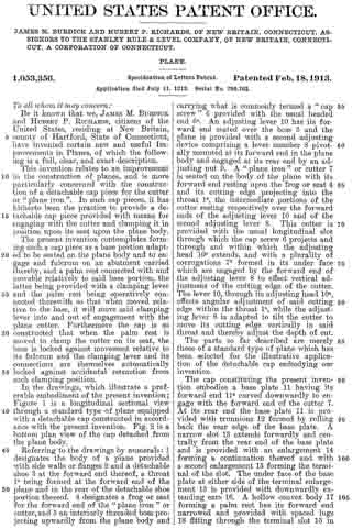
In the drawings, which illustrate a preferable embodiment of the present invention; Figure 1 is a longitudinal sectional view through a standard type of plane equipped with a detachable cap constructed in accordance with the present invention. Fig. 2 is a bottom plan view of the cap detached from the plane body.
Referring to the drawings by numerals: 1 designates the body of a plane provided with side walls or flanges 2 and a detachable shoe 3 at the forward end thereof, a throat le being formed at the forward end of the plane and in the rear of the detachable shoe portion thereof. 4 designates a frog or seat for the forward end of the “plane iron” or cutter, and 5 an interiorly threaded boss projecting upwardly from the plane body and carrying what is commonly termed a “cap screw” 6 provided with the usual headed end 6a. An adjusting lever 10 has its forward end seated over the boss 5 and the plane is provided with a second adjusting device comprising a lever member 8 pivotally mounted at its forward end in the plane body and engaged at its rear end by an adjusting nut 9. A “plane iron” or cutter 7 is seated on the body of the plane with its forward end resting upon the frog or seat 4 and its cutting edge projecting into the throat 1a, the intermediate portions of the cutter resting respectively over the forward ends of the adjusting lever 10 and of the second adjusting lever 8. This cutter is provided with the usual longitudinal slot through which the cap screw 6 projects and through and within which the adjusting head 10a extends, and with a plurality of corrugations 7b formed in its under face which are engaged by the forward end of the adjusting lever 8 to effect vertical adjustment of the cutting edge of the cutter. The lever 10, through its adjusting head 10a, effects angular adjustment of said cutting edge within the throat 1a, while the adjusting lever 8 is adapted to tilt the cutter to move its cutting edge vertically in said throat and thereby adjust the depth of cut.
The parts so far described are merely those of a standard type of plane which has been selected for the illustrative application of the detachable cap embodying our invention.
The cap constituting the present invention embodies a base plate 11 having its forward end 11a curved downwardly to engage with the forward end of the cutter 7. At its rear end the base plate 11 is provided with trunnions 12 formed by rolling back the rear edge of the base plate. A narrow slot 13 extends forwardly and centrally from the rear end of the base plate and is provided with an enlargement 14 forming a continuation thereof and with a second enlargement 15 forming the terminal of the slot. The under face of the base plate at either side of the terminal enlargement 15 is provided with downwardly extending ears 16. A hollow convex body 17 forming a palm rest has its forward end narrowed and provided with spaced lugs 18 fitting through the terminal slot 15 in the base plate and lying in transverse alinement with the ears 16. A link member 19 has its forward end formed as a U shaped bracket 19a and has its rearwardly extending end slotted to form spaced links 19b. The forward bracket end of this link member is seated between the spaced lugs 18 of the palm rest and a pivoted pin 20 is inserted through alining apertures formed in the ear 16, lugs 18 and bracket end 19a of the link member, thereby pivotally connecting the palm rest to the base plate and journaling the link member 19 on the pin 20. A lever member 21 forming in effect a bell crank lever is pivotally mounted at the apex of its angle between the trunnions 12 by means of a pivot pin 22, the lever extending down through the slots 13, 14, and having its lower end formed as a cam 23. The forward end of this bell crank lever is formed with a slot 24 and is positioned between the spaced links 19b at the rear end of link member 19, a pin 25 connecting these links and extending through the slot 24 in the forward end of the lever. The slotted enlargement 14 is of sufficient width to admit the movement of the link ends 19b therethrough and the lugs and the terminal enlargement 15 is of sufficient width to permit the insertion therethrough of the lugs 18 depending from the forward end of the palm rest and positioned between the ears 19 of the base plate 11. It will be evident from the foregoing that when the palm rest 17 is moved on its pivot pin 20 relative to the base plate, it will through the connecting link member 19, move the bell crank lever to bring its cam end into and out of engagement with the cutter 7. The connection of link member 19 with the slotted end of the bell crank lever 21 is such that when the palm rest is moved downwardly to bring the cam end of the lever into cutter clamping position, the link and lever automatically lock themselves against accidental retracting movement. This is caused by the fact that the pin 25 connecting the link member 19 with the bell crank lever 21 is brought below the “dead center” between pivot points 20 and 22 when the palm rest is so moved (see Fig. 1).
The base plate 11 adjacent its forward end and centrally thereof is provided a key-hole slot 26, the enlarged portion of the slot being at the forward end of the base plate and the end of the narrowed portion of the slot rearwardly of the base plate being beveled to conform to the beveling of the head 6a of the cap screw.
With the foregoing construction of the parts in mind the operation and use of the cap is as follows: Assuming that the cutter 7 is seated on the plane body as shown in Fig. 1, with the cap screw 6 extending through the slot 7a therein and the cutter being properly positioned relative to the adjusting devices, the cap with the palm rest raised, is seated thereover by bringing the enlarged end of the key-hole slot 20 over the head of cap screw 6 and then moving the base plate 11 downwardly on the cutter to bring the narrowed portion of the key-hole slot around the head 6a of the cap screw and with the beveled edges of the base plate at the end of said slot abutting against the head 6a. The palm rest 17 may now be moved downwardly this movement causing the base plate to press against and fulcrum on the abutment formed by the headed cap screw 6 and causing the pin 25 carried by the link member 19 to move in the slot 24 of lever 21 and move the cam 23 at the lower end of said lever into frictional clamping engagement with the upper face of the cutter 7 (or when a clamping plate is employed in conjunction with the cutter, into frictional clamping engagement with said plate). The pin 25 will then be beyond the dead center and the link member and clamping lever will therefore be automatically locked against accidental retracting movement. This will also hold the beveled edges of the base plate 11 at the end of the key-hole slot locked against the head 6a of the cap screw abutment thereby affording additional means for preventing movement of the base plate and cap relative to the plane body during service and retaining the cap and its parts in clamping position on the cutter. The degree of frictional clamping engagement of the cam with the cutter is such that the cutter is held fixed on its seat during ordinary service but may be adjusted relative to the cap piece and plane body at any time and by any suitable means without loosening the cap piece or moving it relative to the plane body.
To detach the cap from the plane, it is only necessary to move the palm rest upwardly from the base plate, the application of sufficient force causing the pin 25 to move in slot 24 of the lever and by frictional contact therewith move said lever and its cam end from frictional clamping engagement with the cutter 7. When this has been accomplished, the pressure against the fulcrum head 6a of the cap screw is removed and the base plate 11 may now be moved upwardly on the cutter 7 to bring the enlarged end of its key-hole slot in line with the head of the cam screw, whereupon the cap may be readily detached from the cutter and plane body.
We are aware that the broad combination of elements recited herein is described and claimed in the co-pending application of Christian Bodmer and James M. Burdick, Serial No. 708,733, and lay no claim to such broad combination, our present invention residing in the specific structure embodying such broad combination, as illustrated and described herein and as recited in the appended claims. Furthermore, we desire it understood that while we have described and shown a specific structural embodiment of cap, its structure may be varied in detail within the spirit of the invention and the scope of the appended claims.
What we claim and desire to secure by Letters Patent is:
1. In a plane in combination, a body provided with a cutter seat, a cutter positioned thereon, an abutment carried by said body and a detachable cap comprising a base adapted to be seated over said cutter and engage the forward end thereof and also adapted to engage said abutment, and a palm rest pivotally connected adjacent one end to said base between its ends, a separately formed bell-crank lever pivotally carried by said base in rear of the pivoted end of said palm rest and intermediate the ends of the cap, said lever being provided with a cam member adapted to clamp the cutter on its seat, and said lever being actuated by the movement of said palm rest relative to said base to clamp said cutter on its seat.
2. In a plane, in combination, a body provided with a cutter seat, a cutter positioned thereon, an abutment carried by said body and a detachable cap comprising a base adapted to be seated over said cutter and engage the forward end thereof and also adapted to engage said abutment, and a palm rest pivotally connected adjacent one end of said base between its ends, a separately formed bell-crank lever pivotally carried by said base in rear of the pivoted end of said palm rest and between the ends of the cap, said lever being provided with a cam adapted to clamp the cutter on its seat, operative connections between said palm rest and said bell-crank lever whereby movement of said palm rest relative to said base actuates said lever to clamp said cutter on its seat, said base fulcruming on and being locked against said abutment when the parts are so moved.
3. In a plane, in combination, a body provided with a cutter seat, a cutter positioned thereon, an abutment carried by said body and a detachable cap comprising a base adapted to be seated over said cutter and engage the forward end thereof and also adapted to engage said abutment, and a palm rest pivotally connected adjacent one end of said base between its ends, a separately formed bell-crank lever pivotally carried by said base in rear of the pivoted end of said palm rest and between the ends of the cap, said lever being provided with a cam adapted to clamp the cutter on its seat, operative connections between said palm rest and said bell-crank lever whereby movement of said palm rest relative to said base actuates said lever to clamp said cutter on its seat, said base fulcruming on and being locked against said abutment when the parts are so moved, and said clamping lever and its connection to said palm rest automatically locking themselves against accidental retracting movement.
4. In a plane, in combination, a body provided with a cutter seat, a cutter positioned thereon, an abutment projecting upwardly from said plane body, and a detachable cap for said cutter comprising a base slotted adjacent its rear end, and adapted to be seated over said cutter and engage said abutment, a palm rest having its forward end extending through the slotted portion of said base and pivotally connected to the under side thereof and movable relative thereto, a bell crank lever pivotally mounted at the rear end of said base and extending downwardly through the slot therein and having one end formed as a cam adapted to engage and clamp said cutter on its seat, a link carried by the forward pivoted end of said palm rest, and pin and slot connections between the other end of said lever and said link whereby when said palm rest is moved relative to said base, said cam is moved into and out of clamping engagement with said cutter, said base fulcruming on and being locked against said abutment and said palm rest housing said lever and its connections against accidental displacement when the parts are moved to cutter clamping position.
JAMES M. BURDICK.
HUBERT P. RICHARDS.
Witnesses:
I. W. CHAPMAN,
W. J . WORAM.
Copies of this patent may be obtained for five cents each, by addressing the “Commissioner of Patents, Washington, D. C.”
_________________