| PLEASE NOTE: The images presented on this page are of low resolution and, as a result, will not print out very well. If you wish to have higher resolution files then you may purchase them for only $2.95 per patent by using the "Buy Now" button below. All purchases are via PayPal. These files have all been cleaned up and digitally enhanced and are therefore suitable for printing, publication or framing. Each zip package contains all the images below (some packages may contain more), and purchased files can be downloaded immediately. |
UNITED STATES PATENT OFFICE.
_________________
JOHN P. GAGE, OF VINELAND, NEW JERSEY.
PLANE.
_________________
1,059,137. Specification of Letters Patent. Patented Apr. 15, 1913.
Application filed July 25, 1912. Serial No. 711,586.
_________________
To all whom it may concern:
Be it known that I, JOHN P. GAGE, a citizen of the United States, resident of Vineland, in the county of Cumberland and State of New Jersey, have made a certain new and useful Invention in Planes; and I declare the following to be a full, clear, and exact description of the same, such as will enable others skilled in the art to which it appertains to make and use the invention, reference being had to the accompanying drawings, and to letters or figures of reference marked thereon, which form a part of this specification.
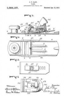
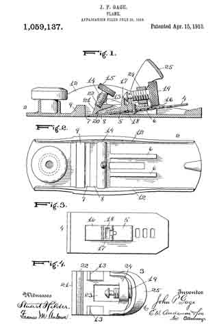
Figure 1 is a central vertical longitudinal section of the invention. Fig. 2 is a detail plan view of the plane stock. Fig. 3 is a detail plan view of the cutting plate and the guide clamp. Fig. 4 is a detail plan view of the cap iron.
The invention is designed to simplify and improve the carpenters’ plane, and particularly the block plane, in such wise as to provide advantages relating to its durability and useful facilities; and it consists in the novel construction and combinations of parts, as hereinafter set forth.
In the annexed drawings the numeral 2 indicates a plane stock; 3 a cap iron; 4 a cutting plate or bit, and 5 a guide clamp which is secured to the bit.
The plane stock is provided with integral inclined bearings 6 on the upper or inner surface of its bottom, in rear of the transverse slot 7 through which the cutting bit is designed to protrude, these bearings coinciding in their inclination with the beveled bearing 8 of the bottom, which extends to the acute rear margin of the slot. The front margin of this slot is formed by a transverse rib 9 which connects the side walls 12, 12, which are substantially parallel and form guides for the movement of the cap iron and bit. Connecting these walls, in the throat of the stock, above and in rear of the slot, is a cross bar or bearing 14, which is perforated and threaded for the passage of a strong set screw 15, the axial direction of which is designed to be substantially in line with that portion of the bottom which is adjacent to the acute edge of the transverse slot. The cutting plate or bit 4 is designed to rest on the bearings 6 and 8, and as the setting and securing devices are located above it, this cutting plate can be disposed at a very low angle, suitable for a plane of the character indicated.
The cutting plate or bit is provided with the usual series of adjustment slots, and on the upper surface of this plate is adjusted and secured the holding or guiding clamp 5, which consists of a longitudinal base portion 16 and an upward projection or lug 17 which is provided with a bearing recess 18, open at its upper end and provided with an open-top slot bearing in rear to receive the neck of an adjusting screw 19. The base of the holding clamp is provided with a threaded aperture for a clamp screw, extending through a slot of the cutter plate. The base of this clamp 5 has parallel sides, and it is designed to engage and slide in a parallel-side recess 20 in the bottom of the cap iron 3. The bottom of the cap iron is plane to lit neatly the top of the bit, at the sides of the clamp lug. The top of the cap iron is made with a beveled front wall 21, a sloping angular bearing 22 in rear of the top of this front wall and lateral bearings or lugs 13 in line with each other and designed to engage the transverse bar 14 of the plane stock when the cap iron is forced into position. The cap iron is provided with a middle opening or slot 23 for the reception of the clamp lug, and in rear of this opening is provided a transverse bearing 24 in which is made a threaded opening for engagement with the adjusting screw 19. The shouldered end of this adjusting screw engages neatly the bearing recess 18 of the clamp lug 5, so that the adjustment of this screw moves the clamp and cutter plate backward or forward with reference to the cap iron, which therefore forms the principal or purchase element for this adjustment.
In a plane of this character the cap iron is designed to be provided with a bowed handle portion or push bearing 25 of sufficient height and span to protect the adjusting screw and allow removal of the cutter and clamp.
The front of the cap iron is of proper height to pass easily under the transverse bar or bearing 14 of the stock. And when the cutting plate, properly and securely fastened to its guide clamp, is provided with its cap iron in engagement with the adjusting screw, a combination of parts is formed which is designed to be placed on the bottom inclines of the stock and, if the set screw 15 is raised, will easily slide forward to position. In normal position the bearings 13 of the cap iron abut against the bar 14 of the stock, and the sloping bearing 22 lies under this bar. The screw 15 being now set down firmly against this sloping bearing, operates to drive the cap iron forcibly home against the transverse bar or bearing 14, and to clamp the cap iron firmly in place on the cutter plate. Adjustment of the bit is easily effected by means of the adjusting screw of the cap iron.
This plane is designed to be in a manner self-setting as its cap iron and plane iron fit together accurately beforehand, and when simply laid in place will slide forward to true position. When the cutting plate is properly secured to its guide clamp, no adjustment of the holding or setting parts is required, except in regard to the operation of the set screw and the adjusting screw. The simple devices of this plane can be taken apart and put together exactly as they were in a few seconds.
The setting and holding devices of the plane are placed above the cutting plate, in such wise that the latter may be arranged at as low an angle as may be required. The cap and plane iron are forced to accurate position and held therein by a single set screw, and without other care and attention than is required to turn the screw forcibly home.
In taking out the bit and cap iron no movement of the adjusting screw is required. The set screw being loosened up sufficiently, the cap iron, guide clamp and cutting plate will slide back and, without moving the adjusting screw, the cap-iron can be lifted from the cutter plate. Upon replacing the parts without adjustment of the screw of the cap iron, the bit takes its former position with relation to the cap iron accurately, so that when placed in the stock the cap iron will take normal position therein and there will be no change in its shaving adjustment. It is designed to provide in this plane practical operating parts which will when once adjusted always go together in accurate and true position with relation to each other to secure the same thickness of shaving without further operation of means of adjustment.
Having described the invention, what I claim and desire to secure by Letters Patent is:
1. In a plane, a stock having a threaded bearing, a cutter plate, a slotted cap iron on said plate having a threaded bearing, a guide clamp for said plate having an upward projecting bearing lug engaging the slot of the cap iron, an adjusting screw in the threaded bearing of the cap iron engaging said bearing lug, and a set screw in the threaded bearing of the stock engaging the cap iron.
2. In a plane, a stock having bottom inclines extending to its cutter slot, a cutter plate, a slotted cap iron provided with an adjusting screw, a guide clamp secured to the upper face of said plate and engaging the slot of the cap iron and having a bearing engaging said adjusting screw, and a set screw for the cap iron engaging a bearing of the stock.
3. In a plane, the combination with a stock having lateral parallel guide walls, bottom inclines and a threaded bearing over said bottom inclincs and a cutting plate engaging said inclines, of a cap iron engaging said guide walls and said cutting plate, a guide clamp for the cutting plate and engaging the cap iron, a set screw engaging the threaded bearing of the stock, and means in connection with said cap iron for adjusting said guide clamp and its plate to said cap iron.
4. In a plane, a stock having bearing and a threaded bearing in its throat, a cap iron having a front sloping bearing and lateral lugs to engage said transverse bearing, a cutter plate, means for adjustably connecting the cutter plate and cap iron and a set screw engaging the threaded bearing of the stock and the sloping bearing of the cap iron.
5. In a plane, a stock having bottom inclines and a threaded transverse bar over the same, a cap iron having a sloping front bearing and lugs to engage said bar, a guiding clamp for the cutter plate having sliding engagement with said cap iron, and means in connection with the latter for adjusting the guiding clamp and its cutter plate.
6. In a plane, the combination with a plane stock having bottom inclines, a threaded bearing over the same and a set screw therein, of a cutter plate on said inclines, a guiding clamp secured to the top of the cutter plate, a cap iron engaging the top of the cutter plate, and an adjusting screw engaging the cutter plate, and an adjusting screw engaging the guide clamp and the cap iron.
7. In a plane, the combination with a plane stock having bottom inclines and a set screw engaging a bearing of said stock above said inclines, of a cutter plate on said inclines, a guiding clamp secured to said cutter plate, an adjusting screw engaging said guiding clamp, and a normally stationary cap iron engaging the stock, the cutter plate, the guiding clamp, the set screw and the adjusting screw.
8. In a plane, a stock having bottom inclines, a set screw engaging a bearing of said stock above said inclines, a cutter plate on said inclines, a guiding clamp secured to the top of said plate, a normally stationary cap iron clamped on top of said plate by the set screw, and an adjusting screw connecting the cap iron and the guiding clamp.
9. A plane having a parallel-wall stock, low bottom inclines, and a bearing of said stock substantially over the cutter slot, a cutter plate on said inclines, a guiding clamp secured to the top of the cutter plate, a normally stationary cap iron on top of said cutter plate, an adjusting screw connecting the cap iron and the guiding clamp, and a set screw in a bearing of said stock engaging said cap iron.
10. In a plane, a parallel-wall stock having a transverse bearing, a cutter plate, a cap iron normally abutting against said bearing, a guiding clamp on top of said cutter plate, an adjusting screw, a set screw, and means in connection with said cap iron and set screw for forcing the cap iron to normal position against said bearing.
11. In a plane, a parallel-wall stock having a threaded transverse bearing in its throat, a cutter plate, a guiding clamp secured to its top, a cap iron engaging said clamp and abutting against the transverse bearing and having a push handle, an adjusting screw connecting said cap iron and guiding clamp, and a set screw engaging said transverse bearing and the cap iron.
12. In a plane, the combination with a parallel-wall stock, a transverse threaded bearing bar in its throat and a set screw in said bar, of a cutter plate, an adjustable clamping guide secured thereon, and a cap iron having normal position abutting said bar and engaged by said set screw.
13. In a plane, the combination with a stock and a threaded transverse bar in its throat, of a cutter plate, a guiding clamp above the cutter plate, a cap iron, means of adjustment connecting the guiding clamp and its cutter plate to the cap iron, and a set screw engaging said threaded transverse bar.
14. A cap iron of a plane having a central guide slot to engage a projection of a clamp for the bit, a threaded bearing in rear of said slot for an adjusting screw to engage said clamp, lateral lugs controlling its normal position in the stock, and a sloping angular bearing adapted to operate under the pressure of a set screw of the stock to force the cap iron to normal position.
15. A plane having in its throat a transverse bearing bar, a cutter plate, movable guiding means for clamping said cutter plate, movable means for adjusting and holding the clamping means, and means in connection withsaid transverse bearing bar for forcing the adjusting and holding means to normal fixed position against said transverse bar.
16. The combination with a parallel-wall stock having a transverse bar and bottom inclines, of a sliding cutter plate, a guide clamp carried thereby, a cap iron engaging said guide clamp, means of adjustment connecting the guide clamp and cap iron, and means for securing the cap iron in its lowest position against the transverse bar.
In testimony whereof I affix my signature, in presence of two witnesses.
JOHN P. GAGE.
Witnesses:
SADIE HOFFMAN,
H. D. STANNARD.
Copies of this patent may be obtained for five cents each, by addressing the “Commissioner of Patents, Washington, D. C.”
_________________

