
| PLEASE NOTE: The images presented on this page are of low resolution and, as a result, will not print out very well. If you wish to have higher resolution files then you may purchase them for only $2.95 per patent by using the "Buy Now" button below. All purchases are via PayPal. These files have all been cleaned up and digitally enhanced and are therefore suitable for printing, publication or framing. Each zip package contains all the images below (some packages may contain more), and purchased files can be downloaded immediately. |
UNITED STATES PATENT OFFICE.
_________________
ALBERT A. PAGE, OF EAST HAVEN, CONNECTICUT, ASSIGNOR TO SARGENT & COMPANY,
OF NEW HAVEN, CONNECTICUT, A CORPORATION OF CONNECTICUT.
PLANE.
_________________
1,090,225. Specification of Letters Patent. Patented Mar. 17, 1914.
Application filed January 26, 1912. Serial No. 673,501.
_________________
To all whom it may concern:
Be it known that I, ALBERT A. PAGE, a citizen of the United States, and resident of the town of East Haven, county of New Haven, and State of Connecticut, have invented new and useful lmprovements in Planes, of which the following is a specification when taken in connection with the accompanying drawing.
This invention relates to planes, and the primary object of the invention is to provide iinproved means for mounting a single adjusting element, such as an adjusting screw, which is capable of adjusting the bit laterally as well as longitudinally. The lateral adjusting rnevernent, which is provided for by a special mounting of the adjusting screw or other element, enables the plane bit to be oscillated to a certain extent relative to the longitudinal axis of the plane so that the cutting edge of the bit may be brought into exact parallelism with the throat in the stock or frame. At the same time, the adjusting screw, or its equivalent, retains its usual function of moving the plane bit longitudinally, i. e., into and out of the throat.
With the foregoing and other objects in view, the invention consists in the novel features and coinbinations of parts to be hereinafter described and claimed.
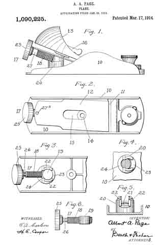
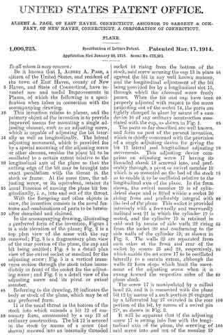
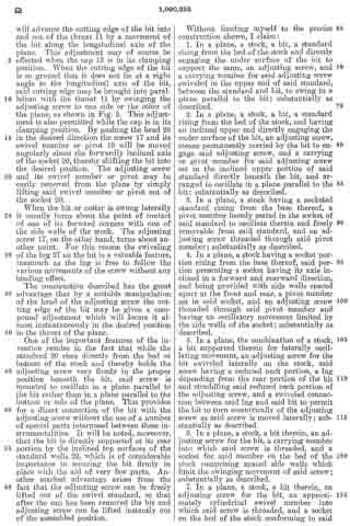
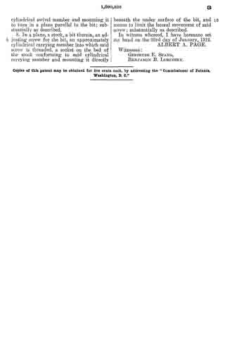
In the accompanying drawing, illustrating a preferred form of the invention, Figure 1 is a side elevation of the plane; Fig. 2 is a top plan view of the same with the cap removed; Fig. 3 is a fraginentary plan view of the rear portion of the plane, the cap and bit being omitted.; Fig. 4 is a detail plan view of the swivel socket or standard for the adjusting screw; Fig. 5 is a vertical transverse section through the stock, taken immediately in front of the socket for the adjusting screw; and F ig. 6 is a detail view of the adjusting screw and its pivot or swivel mernber.
Referring to the drawing, 10 indicates the body or stock of the plane, which may be of any preferred form.
11 is the usual throat in the bottom of the stock into which extends a bit 12 of customary form, surmounted by a cap 13 of ordinary construction. The bit 12 is secured in the stock by means of a screw (not shown) screwed into an internally threaded socket 14 rising from the bottom of the stock, said screw securing the cap 13 in place against the bit in any well known manner, and the longitudinal adjustment of the bit being provided for by a longitudinal slot 15, through which the aforesaid screw freely passes. When the bit and cap have been properly adjusted with respect to the screw projecting out of the socket 14, the parts are tightly clamped in place by means of a cam device 10 of any ordinary construction associated with the cap, as shown in Fig. 1.
The parts so far described are well known, and form no part of the present invention, which is chiefly concerned with the provision of a single adjusting device for giving the bit 12 lateral and longitudinal adjusting movements. This adjusting device comprises an adjusting screw 17 having its threaded shank 18 screwed into, and preferably through, a pivot or swivel member 19 which is so mounted on the bed of the stock as to enable it to be oscillated relative to the longitudinal axis of the plane. In the form shown, the swivel member 19 is of cylindrical shape and is fitled within a socket 20 rising from and preferably integral with the bed of the plane. This socket is provided interiorly with a forwardly and rearwardly inclined seat 21 in which the cylinder 19 is seated, and the cylinder 19 is retained in said seat by means of side walls 22 rising froin the socket 20 and conforming to the side walls of the cylinder 19, as shown in Fig. 3. The walls 22 are separated from each other at the front and rear of the socket by spaces 23 and 24, respectively, which enable the set screw 17 to be oscillated laterally to a certain extent, altliough the walls 22 form stops which limit the movement of the adjusting screw when it is swung toward the respective sides of the plane stock.
The screw 17 is manipulated by a milled head 25, and it is connected with the plane bit 12 by means of a neck portion 26 engaged by a bifurcated lug 27 swiveled in the rear portion of the bit, by means of a swivel pin 27a, as shown in Fig. 2.
It will be apparent that if the adjusting screw 17 is swung into line with the longitudinal axis of the plane, the screwing of said screw into and out of the member 19 will advance the cutting edge of the bit into and out of the throat 11 by a movement of the bit along the longitudinal axis of the plane. This adjustment may of course be effected when the cap 13 is in its clamping position. When the cutting edge of the bit is so ground that it does not lie at a right angle to the longitudinal axis of the bit, said cutting edge may be brought into parallelism with the throat 11 by swinging the adjusting screw to one side or the other of the plane, as shown in Fig. 2. This adjustment is also permitted while the cap is in its clamping position. By pushing the head 25 in the desired direction the screw 17 and its swivel member or pivot 19 will be moved angularly about the forwardly inclined axis of the socket 20, thereby shifting the bit into the desired position. The adjusting screw and its swivel member or pivot may be easily removed from the plane by simply lifting said swivel member or pivot out of the socket 20.
When the bit or cutter is swung laterally it usually turns about the point of contact of one of its forward corners with one of the side walls of the stock. The adjusting screw 17, on the other hand, turns about another point. For this reason the swiveling of the lug 27 on the bit is a valuable feature, inasmuch as the lug is free to follow the various movements of the screw without any binding effect.
The construction described has the great advantage that by a suitable manipulation of the head of the adjusting screw the cutting edge of the bit may be given a compound adjustment which will locate it almost instantaneously in the desired position in the throat of the plane.
One of the important features of the invention resides in the fact that while the standard 20 rises directly from the bed or bottom of the stock and thereby holds the adjusting screw very firmly in the proper position beneath the bit, said screw is mounted to oscillate in a plane parallel to the bit rather than in a plane parallel to the bottom or sole of the plane. This provides for a direct connection of the bit with the adjusting screw without the use of a number of special parts interposed between these instrumentalities. lt will be noted, moreover, that the bit is directly supported at its rear portion by the standard walls importance in place with the other marked inclined top surfaces of the 22, which is of considerable securing the bit firmly in aid of very few parts. An advantage arises from the fact that the adjusting screw can be freely lifted out of the swivel standard, so that after the cap has been removed the bit and adjusting screw can be lifted instantly out of the assembled position.
Without limiting myself to the precise construction shown, I claim:
1. ln a plane, a stock, a bit, a standard rising from the bed of the stock and directly engaging the under surface of the bit to support the same, an adjusting screw, and a carrying member for said adjusting screw swiveled in the upper end of said standard, between the standard and bit, to swing in a plane parallel to the bit; substantially as described.
2. ln a plane, a stock, a bit, a standard rising from the bed of the stock, and having an inclined upper end directly engaging the under surface of the bit, an adjusting screw, means permanently carried by the bit to engage said adjusting screw, and a carrying or pivot member for said adjusting screw set in the inclined upper portion of said standard directly beneath the bit, and arranged to oscillate in a plane parallel to the bit; substantially as described.
3. ln a plane, a stock having a socketed standard rising from the base thereof, a pivot member loosely seated in the socket of said standard to oscillate therein and freely removable from said standard, and an adjusting screw threaded through said pivot member; substantially as described.
4. In a plane, a stock having a socket portion rising from the base thereof, said portion presenting a socket having its axis inclined in a forward and rearward direction, and being provided with side walls spaced apart at the front and rear, a pivot member set in said socket, and an adjusting screw threaded through said pivot member and having an oscillatory movement limited by the side walls of the socket; substantially as described.
5. ln a plane, the combination of a stock, a bit supported therein for laterally oscillating movement, an adjusting screw for the bit swiveled laterally on the stock, said screw having a reduced neck portion, a lug depending from the rear portion of the bit and straddling said reduced neck portion of the adjusting screw, and a swiveled connection between said lug and said bit to permit the bit to turn eccentrically of the adjusting screw as said screw is moved laterally; sub-
stantially as described.
6. In a plane, a stock, a bit therein, an adjusting screw for the bit, a carrying member into which said screw is threaded, and a socket for said member on the bed of the stock comprising spaced side walls which limit the swinging movement of said screw; substantially as described.
7. ln a plane, a stock, a bit therein, an adjusting screw for the bit, an approximately cylindrical swivel member into which said screw is threaded, and a socket on the bed of the stock conforming to said cylindrical swivel member and mounting it to turn in a plane parallel to the bit; substantially as described.
8. In a plane, a stock, a bit therein, an adjusting screw for the bit, an approximately cylindrical carrying member into which said screw is threaded, a socket on the bed of the stock conforming to said cylindrical carrying member and mounting it directly beneath the under surface of the bit, and means to limit the lateral movement of said screw; substantially as described.
In witness whereof, I have hereunto set my hand on the 23rd day of January, 1912.
ALBERT A. PAGE.
Witnesses:
GERTRUDE E. SPANG,
BENJAMIN B. LUBINSKY.
Copies of this patent may be obtained for five cents each, by addressing the “Commissioner of Patents, Washington, D. C.”
_________________