

| PLEASE NOTE: The images presented on this page are of low resolution and, as a result, will not print out very well. If you wish to have higher resolution files then you may purchase them for only $2.95 per patent by using the "Buy Now" button below. All purchases are via PayPal. These files have all been cleaned up and digitally enhanced and are therefore suitable for printing, publication or framing. Each zip package contains all the images below (some packages may contain more), and purchased files can be downloaded immediately. |
UNITED STATES PATENT OFFICE.
_________________
ALBERT A. PAGE, OF EAST HAVEN, CONNECTICUT, ASSIGNOR TO SARGENT & COMPANY,
OF NEW HAVEN, CONNECTICUT, A CORPORATION OF CONNECTICUT.
RABBET-PLANE.
_________________
1,100,770. Specification of Letters Patent. Patented June 23, 1914.
Application filed February 9, 1912. Serial No. 676,661.
_________________
To all whom it may concern:
Be it known that I, ALBERT A. PAGE, a citizen of the United States, and resident of the town of East Haven, county of New Haven, and State of Connecticut, have invented certain new and useful Improvements in Rabbet-Planes, of which the following is a full, clear, and exact description.
This invention relates to rabbet planes, and the primary object of the invention is to provide a plane having an improved form of guiding extension cooperating with the main part of the stock to form a throat for the bit and adjustably and detachably connected in an improved manner with the stock.
By my improvements, the guiding extension may be firmly clamped in the desired adjustment, when used for ordinary planing, with the throat adjusted to a width suitable to the conditions which obtain in any given case, and when planing in a corner or close to a wall, or the like, the extension may be very readily detached and bodily removed so that the tool will be converted into a bull nose plane. The main part of the stock is provided with a suitable grip portion or palm rest which is equally edective when the tool is used as an ordinary plane or as a bull nose plane.
To these and other ends, the invention consists in the novel features and combinations of parts to be hereinafter described and claimed.
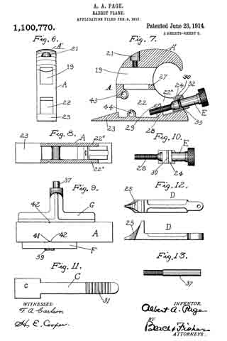
In the accompanying drawings, in which I have illustrated a preferred embodiment of the invention, Figure 1 is a side elevation of the plane; Fig. 2 is a similar view, taken from the opposite side, the forward extension on the stock being removed; Fig. 3 is a front elevation of the plane; Fig. 4 is a transverse section on line 4–4 of Fig. 1; Fig. 5 is a front view of Fig. 2, with the gages removed; Fig. 6 is a front elevation of the body or stock; Fig. 7 is a vertical longitudinal section through the stock showing the lengthwise adjusting screw for the bit in position therein; Fig. 8 is a horizontal longitudinal section through the stock; Fig. 9 is a bottom view of the stock, with the gages in position; Fig. 10 is a detail view of the adjusting screw; Fig. 11 is a bottom plan view of the bit or plane iron; Fig. 12 shows in plan and in side elevation the clamping lever or cap piece for the bit; and Fig. 13 is a detail view of the pin on which the width gage is mounted.
Referring to the drawings, the stock A is shown as provided with a forwardly directed detachable extension B adapted to form in conjunction with the lower forward edge of the stock a throat a’ (Fig. 1), into which projects a bit or plane iron C, secured in the stock by means of a cap piece or clamping lever D. The bit or plane iron C is adjusted longitudinally by means of an adjusting screw E, and at one side of the stock is a vertically adjustable depth gage F, while at the opposite side a horizontally adjustable width gage G is provided. At the top of the stock A, the same is provided with a suitably formed grip portion or palm rest A’ independent of the extension B.
Referring now to the detailed construction of the parts above mentioned, it will be observed that the forward extension B carried by the stock comprises an arm 15, carrying a foot or guide 16, disposed in advance of the bit, and having its smooth lower portion flush with the bottom face of the stock A. The foot or guide 16 is provided at the top with an upwardly directed gripping projection 17, and it is connected with the arm or bar 15 by means of a downwardly curved portion 18. The arm or bar 15 is adjustable longitudinally of the stock in a longitudinal opening 19, extending through the upper part of the latter, as best shown in Fig. 7, the extension B being clamped in the desired longitudinal adjustment by means of a set screw 20, shown in dotted lines in Figs. 1 and 2, screwed into a counter-bored opening 21 at the upper portion of the stock or body A. By loosening this set screw the extension B may be slid lengthwise of the stock in order to vary as desired the width of the throat a’, and in certain cases, as when planing in a corner, the extension B may be altogether removed.
The lower portion of the body A, beneath the guide opening 19 for the extension B, is provided with a longitudinal opening or chamber 22 (Fig. 7) through which extend the bit C and cap piece D. The bit C rests at its laterally enlarged end c on a beveled foot or extension 23 formed integral with and extending forwardly from the lower front portion of the body A, and at its rear portion it is supported on an adjusting block 24 carried by the adjusting screw E. On top of the bit lies the cap piece or clamping lever D, having at its forward end a nose or enlargement 25 bearing on the front end portion of the bit, and having at its rear end a threaded opening for a clamping screw 20. This screw bears at its lower end against the upper face of the bit, near the rear end of the latter, and as said screw is screwed through the cap piece D (bearing meanwhile on the upper face of the bit) the cap piece will be raised into a position wherein its rear portion abuts a bridge 27 at the rear of the stock (Fig. 7), thereby pressing the nose 25 and clamping screw 26 tightly against the respective ends of the bit. In this manner, the bit may be firmly clamped in position without the use of a pivot screw, or the like, for the clamping lever or cap piece.
The adjusting screw E is provided with a threaded shank 28 engaging an interiorly threaded lug 29 extending upward from the bottom of the stock beneath the bit. Hence, by screwing the screw E in one or the other direction, it will be advanced into or retracted from the stock, carrying with it the block 24. This block is provided at its upper portion with a cross-rib 30 adapted to engage any of a number of transverse grooves 31 on the under face of the bit, so that the bit will partake of the adjusting movement of the block. The latter is guided rectilinearly between the side walls 22x of the stock, it being secured to the screw E by means permitting the relative rotation of the screw and block, but preventing independent longitudinal movements thereof. In the embodiment shown, this means comprises a pin 32 extending transversely across the block and engaging a transverse groove 33 in the body portion of the adjusting screw, as shown in Fig. 7.
The width gage G is preferably formed as a casting of appropriate shape having a finished face 34 directed at right angles to the bottom of the stock and likewise equipped with a sleeve 35 and set screw 36, by means of which the gage is adjustable transversely of the stock on a supporting pin 37 projecting laterally from the stock, as shown in Fig. 3. The depth gage F, on the opposite side of the stock, preferably consists of a plate, having a finished foot portion 33 movable vertically alongside the stock, said plate being clamped in the desired vertical position by means of a set screw 39 engaging a vertical slot 40 in the plate, as shown in Fig. 1. The depth gage F is guided in its vertical movement by means of a tang or projection 41 (Fig. 9) extending from the rear or inner face of the foot 38, and engaging a vertical groove 42 in the side of the stock.
The width and depth gages are preferably reversible, and to this end the opening 43 (Figs. 2 and 7) for the set screw 30 extends completely through the stock, and there is a guide groove 42 on each side of the stock, as shown in Fig. 9. The width gage G is made reversible by extending the opening or socket 44 (Fig. 7) for the pin 37 completely through the body of the stock. In this manner, the pin 37 with the width gage mounted thereon may be fixed to the stock at either side, the depth gage being placed on the opposite side.
In doing work which is readily accessible, the extension B is secured to the stock in the desired adjustment, the width of the throat a’ being optional. The extension not only serves as a guide for the stock, but also as a gripping member to increase the facility with which the tool may be handled. With the extension removed, the tool is converted into a very handy bull nose plane. When working in a corner, the extension may be easily removed by loosening the screw 20, and there will then be nothing to prevent the passage of the forward bit edge completely up to the walls defining the corner, as will be understood. The grip portion or palm rest A’ of the stock, being independent of the removable extension, is equally effective when the plane is used as an ordinary plane, or as a bull nose plane.
Of course, it will be obvious that while the foregoing description is a detailed one, in so far as it concerns the particular embodiment of my invention selected for illustration, the invention is susceptible of many other embodiments within the scope of the appended claims.
What I claim is :–
l. In a plane, a stock having a longitudinal opening, a bit in said stock and a guiding extension for the plane comprising a guiding foot cooperating with the stock to form a throat for said bit, and also comprising a bar adjustable longitudinally in said opening of the stock; substantially as described.
2. In a plane, a stock having a longitudinal opening extending completely therethrough, a bit carried by the stock, a bar movable longitudinally in said opening of the stock, a set screw to clamp said bar in the desired adjustment, and a guiding foot carried by said bar and forming in connection with the stock a throat for the bit; substantially as described.
3. In a plane, the combination of a stock having a grip portion or palm rest at the upper part thereof, a bit, means mounting said bit in said stock, beneath said palm rest, so that the cutting edge of the bit is located at the forward extremity of the stock, and a detachable guiding extension for said stock, comprising a foot forming in connection with the forward extremity of the stock a throat for the bit, and a carrying element for said foot adjustable forwardly and rearwardly in the upper portion of the stock; substantially as described.
4. In a plane, the combination of a stock having a forwardly and rearwardly directed opening at the upper part thereof, and a second forwardly and rearwardly directed opening beneath said first named opening, a guiding extension adjustably fitted in said first named opening, and a bit adjustably secured in said second opening; substantially as described.
5. In a plane, the combination of a stock having at its upper part a forwardly and rearwardly directed opening, a guiding extension adjustably secured in said opening, a grip portion or palm rest on the stock above said opening, and a bit secured in the stock beneath said opening; substantially as described.
6. In a plane, the combination of a stock having a grip portion or palm rest and a depending foot at the upper or top part thereof, a guiding extension, including a bar adjustable forwardly and rearwardly in said stock beneath said palm rest, and a bit secured in said stock and projecting into a throat between said guiding extension and the forward end of the stock; substantially as described.
7. In a plane, the combination of a stock having a palm rest at the top thereof and provided with a forwardly and rearwardly directed opening beneath said palm rest, said stock being further provided beneath said opening with a second opening, extending through the stock from front to rear, a bit secured in said second opening, and a forwardly directed guiding extension, including a bar adjustable lengthwise in said first opening, cooperating with the forward end of the stock to create a throat for said bit; substantially as described.
8. In a plane, the combination with a stock hollowed out from front to rear to present a bit opening extending completely therethrough, a bit in said opening, a clamping piece resting on said bit within said opening and extending out of said opening at the rear of the stock, and a clamping screw carried by said clamping piece and engaged with the bit to force said clamping piece against the upper edge of said bit opening at the rear of the stock, and thereby clamp the bit in position; substantially as described.
9. In a plane, the combination of a stock having a palm rest at the top, and a longitudinal opening beneath said palm rest, a bit secured in said stock beneath said opening with its cutting edge at the front extremity of the stock, and a guiding extension comprising a foot in advance of the bit, a bar adjustable lengthwise in said opening, and a downwardly directed portion connecting said bar with said foot; substantially as described.
In witness whereof, I have hereunto set my hand on the 7th day of February, 1912.
ALBERT A. PAGE.
Witnesses:
CURTIS P. WILLIAMS,
BERTHA RAY.
Copies of this patent may be obtained for five cents each, by addressing the “Commissioner of Patents, Washington, D. C.”
_________________