
| PLEASE NOTE: The images presented on this page are of low resolution and, as a result, will not print out very well. If you wish to have higher resolution files then you may purchase them for only $2.95 per patent by using the "Buy Now" button below. All purchases are via PayPal. These files have all been cleaned up and digitally enhanced and are therefore suitable for printing, publication or framing. Each zip package contains all the images below (some packages may contain more), and purchased files can be downloaded immediately. |
United States Patent Office.
JOSEPH JONES, OF NEWARK, NEW JERSEY.
Letters Patent No. 110,765, dated January 3, 1871.
_________________
IMPROVEMENT IN CARPENTERS’ SHOOTING-BOARDS.
_________________
The Schedule referred to in these Letters Patent and making part of the same.
_________________
I, JOSEPH JONES, of the city of Newark, in the county of Essex and State of New Jersey, have invented certain Improvements in the Carpenter’s Shooting-Board secured to me by Letters Patent, No. 52,719, issued February 20, 1866, of which improvements the following is a specification.
The first improvement relates to the bed-piece upon which the piece of wood lies to be planed;
The second relates to the stop and to its adjustment ; and
The third to an addition to the stop.
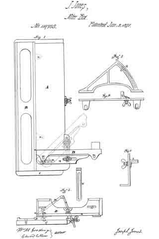
Figure 1 is a plan of the bed-piece, showing the improvements in both bed-piece and stop;
Figure 2 is an end view of the same;
Figure 3 is the additional attachment to the stop;
Figure 4 is a top view; and
Figure 5 is an end view of the same.
A is the bed-piece, which, from the end y to the stop, is a separate piece from the main frame;
B is the main frame;
C is the base-board; and
D, the stop.
In providing for the elevation of the bed-piece A, it is essential that its upper edge, next to the face of the plane, should be the center of motion, remaining close to the face of the plane, while the lower edge recedes therefrom, as the bed-piece is turned up to a required angle. To this end two rods, X, each a segment of a circle, whose center is at z on the upper edge-line of the bed-piece, are attached to and form part of the bed-piece A, and move in guides in the main frame B.
Upon the edge of the base-board C is a hinged screw-bolt, V; and to the back edge of the bed-piece there is attached a slotted bar, W.
The hinged bolt V goes through the slot in the bar W, and the bar is held in position by the thumb-nut n, securing the bed-piece A at any required angle of inclination.
The frame B has, from the end of the bed-piece A, at z, its upper face level with the bed-piece, when that bed-piece lies flat on the frame, upon which level face the stop D is secured.
t and u (the latter shown by dotted lines in fig. 1) show two slots in the level face, placed at right angles to each other.
A pin, r, passes through the slot u and the foot-piece q of the stop D, and a bolt, with a thumb-screw or nut, s, also passes through the foot-piece q and through a slot, t, in the frame, by which the stop is made easily adjustable to any required angle, and is held securely in place on the frame.
As an additional support to long stuff when having a bevel planed on its end, the frame, fig. 3, is made conveniently attachable to and detachable from the stop D.
In the outer bar of that frame is a semicircular slot, which is a segment of a circle, whose center is z on the main frame.
A projecting support, k, held by a thumb-screw, is by those means adjustable, as may be required, to any desired inclination.
Thus, having described my improvements, What I claim and desire to secure by Letters Patent, is —
The bed-plate B and adjustable table A, in combination with the stop D, all the parts being constructed, arranged, and operating in the manner and for the purpose as shown and described.
JOSEPH JONES.
Witnesses:
WM. M. GOODING,
EDWARD COLLVER.