| PLEASE NOTE: The images presented on this page are of low resolution and, as a result, will not print out very well. If you wish to have higher resolution files then you may purchase them for only $2.95 per patent by using the "Buy Now" button below. All purchases are via PayPal. These files have all been cleaned up and digitally enhanced and are therefore suitable for printing, publication or framing. Each zip package contains all the images below (some packages may contain more), and purchased files can be downloaded immediately. |
UNITED STATES PATENT OFFICE.
_________________
HARVEY M. WOOD, OF LOS ANGELES, CALIFORNIA.
BENCH-PLANE.
_________________
1,112,399. Specification of Letters Patent. Patented Sept. 29, 1914.
Original application filed November 8, 1907. Serial No. 401,341. Divided and this application filed October
14, 1912. Serial No. 725,577.
_________________
To all whom it may concern:
Be it known that I, HARVEY M. WOOD, a citizen of the United States, residing at Los Angeles, in the county of Los Angeles and State of California, have invented a new and useful Bench-Plane, of which the following is a specification.
The object of this invention is to protect the cutting edge of the blade during the backward stroke of the plane and while standing idle on its sole, this result being attained by use of a heel-piece yieldingly projecting through and beyond the sole and serving to normally uphold the same above the table top.
This application is a division of my co-pending application for patent on bench plane, Serial No. 401,341, filed Nov. 8, 1907.
The accompanying drawings illustrate the invention.
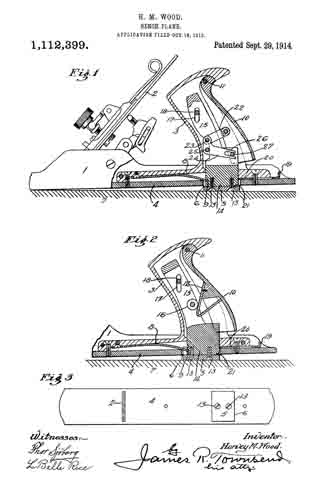
Figure 1 is a side elevation partly in mid-section, showing the details of the heel-piece and the symmetrical mechanism for operating the same. Fig. 2 is a similar view showing a modification of the mechanism for operating the heel-piece. Fig. 3 is a reduced plan of the bottom of either of the planes shown in Figs. 1 and 2.
Numeral 1 refers to the shoe of an ordinary plane having a blade 2, hollow handle 3, sole 4, and yieldingly extended retractible heel-piece 5, the latter projecting normally through aperture 6 and extending substantially across the sole. A spring 8, fixed to the shoe and engaging notch 9 in the heel-piece normally projects the heel-piece through the sole so that when the plane rests loosely upon the work or on the bench top 7, or is being drawn backward over the same, the heel and the cutting edge will be raised off the work as shown in the drawings, thus saving the cutting edge from all unnecessary contact and preserving its keenness. On the forward or planing stroke, however, it is essential that the cutting edge come onto the work immediately and manually operated means are provided whereby the forward pressure of the workman’s hand in the operation of planing, will automatically retract the heel-piece. With this object in view, there is provided a rear handle section or palm piece 10, suitably connected with the heel-piece to retract it into the shoe and permit the sole and cutting edge to come down onto the work. The heel-piece 5 may be unitarily constructed with, or may be attached by screws 13 to a carrier block 14 having uprights 15 and vertically movable in the shoe; the uprights being provided with vertical slots 17 running on a pintle 18 rigidly mounted in the handle and thus assisting in guiding the carrier and heel-piece.
In the form shown in Fig. 1, linkage is provided for retracting the heel-piece. The link 22 is pivotally mounted at one end on the palm piece 10 and is pivotally connected at the other end by pin 23 to a bell-crank 24 that is pivotally supported on the handle by means of the pivot 25, and that is provided at its operating end with a forked arm 26, the prongs of which cooperate with pin 27 to retract the heel-piece and carrier. By this means the heel-piece will be automatically retracted in an obvious manner by the forward pressure of the workman’s hand on the palm piece during the cutting stroke.
In the form shown in Fig. 2, the palm piece 10 carries a downwardly and forwardly inclined cam member 12, adjacent which the uprights are provided with a revolubly mounted cam follower 16 adapted to cooperate with the cam member 12 to raise the carrier block and heel-piece when the palm piece 10 is pressed forward. A latch comprising a finger piece 19 and stop 20 is provided to engage a notch 21 of the heel-piece to hold the heel-piece retracted with its face flush with the sole. When the heel-piece is latched, the plane operates like an ordinary plane during both the forward and return strokes.
I claim :–
1. In a plane the combination of a shoe, a blade, a handle behind said blade, said handle being rigidly mounted on said shoe, and said handle having a rear member movably mounted, a heel-piece arranged to normally project beyond the shoe, and means connecting the said rear member of the handle with the heel-piece and adapted to retract the said heel-piece when the rear section of the handle is moved.
2. In a plane the combination of a shoe, a blade, a spring operated heel-piece arranged to normally project beyond the shoe, a handle behind said blade, said handle being rigidly mounted on said shoe, and said handle having a movably mounted rear section, means connecting the said rear section of the handle with the heel-piece and adapted to retract the said heel-piece when the rear section of the handle is moved, and means for holding said heel-piece in its retracted position.
3. In a plane, the combination of a shoe, a blade, a hollow handle having a rear section pivotally mounted, a spring-operated heel-piece adapted to normally project beyond the shoe and mechanism in the hollow of the handle connecting the rear section of the handle with the heel-piece and adapted to retract the heelfpiece when the rear sec-
tion of the handle is moved.
4. In a plane the combination of a shoe, a blade, a hollow handle having a rear section pivotally mounted, a spring operated heel-piece adapted to normally project beyond the shoe, and link mechanism supported in the hollow of the handle and connecting the rear section of the handle with the heel-piece and adapted to retract the heel-piece when the rear section of the handle is moved.
5. In a plane the combination of a shoe, a blade, a hollow handle having a rear section pivotally mounted, a carrier riding in the hollow of the handle, a heel-piece mounted on the carrier and adapted to normally project through and beyond the shoe, and means in the hollow of the handle connecting the rear section of the handle with the carrier and adapted to retract the carrier and heel-piece by motion of the rear section of the handle.
6. In a plane the combination of a shoe, having a sole, a blade, a hollow handle having a rear section pivotally mounted, a heel-piece adapted to normally project beyond the sole, a bell-crank mounted within the handle and having a forked arm, a link connecting one arm of the bell-crank with the rear section of the handle, and a pin mounted on the heel-piece and cooperating with the forked arm of the bell-crank to be raised by the same.
7. In a plane, the combination with a shoe, a blade and a handle behind said blade, of a spring-operated heel-piece carried by said handle and arranged to lift the heel of the plane, and manually operated means for retracting said heel-piece.
8. In a plane, the combination with a shoe, a blade and a handle behind said blade, of a spring-operated heel-piece carried by said handle and arranged to lift the heel of the plane, means for retracting said heel-piece, and means for holding said heel-piece in its retracted position.
9. A plane comprising a sole, a handle fixed to said sole and provided with a movable palm-piece, and a heel piece operatably connected to the palm-piece and normally below the plane of the sole and adapted to be raised by movement of said palm-piece.
In testimony whereof, I have hereunto set my hand at Los Angeles, California, this 28th day of September 1912.
HARVEY M. WOOD.
In presence of —
JAMES R. TOWNSEND,
ROBERT A. STEPS.
Copies of this patent may be obtained for five cents each, by addressing the “Commissioner of Patents, Washington, D. C.”
_________________


