
| PLEASE NOTE: The images presented on this page are of low resolution and, as a result, will not print out very well. If you wish to have higher resolution files then you may purchase them for only $2.95 per patent by using the "Buy Now" button below. All purchases are via PayPal. These files have all been cleaned up and digitally enhanced and are therefore suitable for printing, publication or framing. Each zip package contains all the images below (some packages may contain more), and purchased files can be downloaded immediately. |
UNITED STATES PATENT OFFICE.
_________________
LEONARD BAILEY, OF NEW BRITAIN, CONNECTICUT.
IMPROVEMENT IN PLANE-STOCKS.
_________________
Specification forming part of Letters Patent No. 113,003, dated March 28, 1871.
_________________
I, LEONARD BAILEY, of New Britain, in the county of Hartford and State of Connecticut, have invented certain Improvements in Flexible-Faced Plane-Stocks, of which the following is a specification:
My invention consists in the combination of the parts, as hereinafter described.
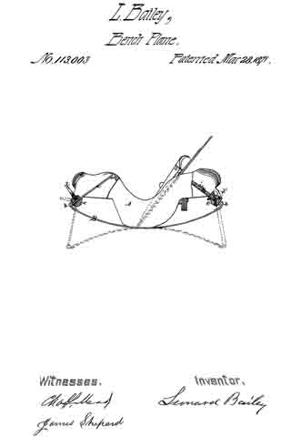
The accompanying drawing shows a side elevation, partly in section, of a plane-stock of my invention.
A designates the stock proper, which I prefer to make of cast metal; but it may be made of any suitable material. B designates the flexible face-plate, which is made of spring-steel, and secured to the under side of the stock A, near the center of its length, by screws or rivets, in the ordinary manner.
At each end of the face-plate B is secured an arm, a a’, connected thereto by means of a suitable hinge, b b’. The arms a a’ pass through the rocking shafts c c’, which shafts are pivoted in each end of the stock A, in such manner as to easily rock or partially rotate.
By means of the set-screw d (shown at the left in the drawing) the arm a may be secured firmly in the rocking shaft c; or, if desired, the arm a’ may be threaded and held in place by a nut, d’, upon each side of the rocking shaft, as shown at the right in the drawing.
The peculiar mechanism employed to secure or fasten the arms a a’ in the rock-shafts c is immaterial to my invention. Each end of the stock A is made hollow or open, to allow free play to the arms af a a’.
The broken lines in the drawing indicate the position of the arms a a’ and faceplate B, with the latter bent into a concave form.
By releasing the set-screw d, so as to allow the arm a, to pass freely through the rocking shaft c, the ends of the face-plate B may be bent upward, forming the latter into a convex form.
The movement of either arm a a’, in passing through the shaft c causes said shaft to rock on its pivots, when the end n, of such arm a a’ moves in an inward as well as upward direction, and rests (when the ends of the face-plate B are bent upward to their full capacity) in the hollow of the stock A, as shown in the drawing.
The face-plate B may be set with its ends at any point between the two positions herein shown.
I claim as my invention —
In a flexible-faced plane-stock, substantially as described, the rocking shaft c c, pivoted in the stock A, and receiving the arms a, a’ of the face-plate B, all substantially as and for the purpose described.
LEONARD BAILEY.
Witnesses:
JAMES SHEPARD,
CHAS. L. MEAD.