

| PLEASE NOTE: The images presented on this page are of low resolution and, as a result, will not print out very well. If you wish to have higher resolution files then you may purchase them for only $2.95 per patent by using the "Buy Now" button below. All purchases are via PayPal. These files have all been cleaned up and digitally enhanced and are therefore suitable for printing, publication or framing. Each zip package contains all the images below (some packages may contain more), and purchased files can be downloaded immediately. |
UNITED STATES PATENT OFFICE.
_________________
CHRISTIAN BODMER, OF NEW BRITAIN, CONNECTICUT, ASSIGNOR. TO THE STANLEY RULE &
LEVEL COMPANY, OF NEW BRITAIN, CONNECTICUT, A CORPORATION OF CONNECTICUT.
PLANE.
_________________
1,134,072. Specification of Letters Patent. Patented Mar. 30, 1915.
Application filed November 5, 1914. Serial No. 870,356.
_________________
To all whom it may concern:
Be it known that I, CHRISTIAN BODMER, a citizen of the United States, residing at New Britain, county of Hartford, State of Connecticut, have invented certain new and useful Improvements in Planes, of which the following is a full, clear, and exact description.
My invention relates to that class of planes commonly termed “dado” planes, the main function of which is to cut a groove across a grain of a piece of wood. Such a plane should be so constructed as to effectively score the wood ahead of the cutter.
One of the objects of my invention is to provide a simple and improved device for performing this operation.
Another object is to provide an improved plane body, so designed as to reliably carry the various parts thereon, said parts being so placed and spaced as to render the plane easy to operate, and under perfect control at all times.
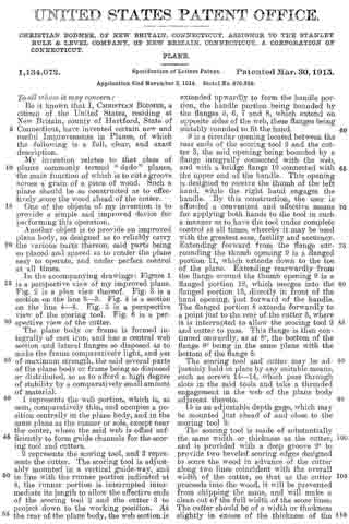
In the accompanying drawings: Figure 1 is a perspective view of my improved plane. Fig. 2 is a plan view thereof. Fig. 3 is a section on the line 3–3. Fig. 4 is a section on the line 4–4. Fig. 5 is a perspective view of the scoring tool. Fig. 6 is a perspective view of the cutter.
The plane body or frame is formed integrally of cast iron, and has a central web section and lateral flanges so disposed as to make the frame comparatively light, and yet of maximum strength, the said several parts of the plane body or frame being so disposed or distributed, so a.s to afford a high degree of stability by a comparatively small amount of material.
1 represents the web portion, which is, as seen, comparatively thin, and occupies a position centrally in the plane body, and in the same plane as the runner or sole, except near the center, where the said web is offset sufficiently to form guide channels for the scoring tool and cutters.
2 represents the scoring tool, and 3 represents the cutter. The scoring tool is adjustably mounted in a vertical guide-way, and in line with the runner portion indicated at 4, the runner portion is interrupted intermediate its length to allow the effective ends of the scoring tool 2 and the cutter 3 to project down to the working position. At the rear of the plane body, the web section is extended upwardly to form the handle portion, the handle portion being bounded by the flanges 5, 6, 7 and 8, which extend on opposite sides of the web, these flanges being suitably rounded to at the hand.
9 is a circular opening located between the rear ends of the scoring tool 2 and the cutter 3, the said opening being bounded by a flange integrally connected with the web, and with a bridge flange 10 connected with the upper end of the handle. This opening is designed to receive the thumb of the left hand, while the right hand engages the handle. By this construction, the user is afforded a convenient and effective means for applying both hands to the tool in such a manner as to have the tool under complete control at all times, whereby it may be used with the greatest ease, facility and accuracy. Extending forward from the flange surrounding the thumb opening 9 is a flanged portion 11, which extends down to the toe of the plane. Extending rearwardly from the flange around the thumb opening 9 is a flanged portion 12, which merges into the fianged portion 13, directly in front of the hand opening, just forward of the handle. The flanged portion 3 extends forwardly to a point just to the rear of the cutter 3, where it is interrupted to allow the scoring tool 2 and cutter to pass. This flange is then continued onwardly, as at 8a, the bottom of the flange 8a being in the same plane with the bottom of the flange 8.
The scoring tool and cutter may be adjustably held in place by any suitable means, such as screws 14–14, which pass through slots in the said tools and take a threaded engagement in the web of the plane body adjacent thereto.
15 is an adjustable depth gage, which may be mounted just ahead of and close to the scoring tool 2.
The scoring tool is made of substantially the same width or thickness as the cutter, and is provided with a deep groove 2a to provide two beveled scoring edges designed to score the wood in advance of the cutter along two lines coincident with the overall width of the cutter, so that as the cutter proceeds into the wood, it will be prevented from chipping the same, and will make a clean cut of the full width of the score lines. The cutter should be of a width or thickness slightly in excess of the thickness of the runner 4, so that said runner 4 will not jam in the groove, and yet will be sufficiently steadied thereby to guide the cutter.
It will be observed that the flanges by extending on both sides of the web, reinforce the same and prevent buckling. Also that the lower flange forms a substantially flat sole below which extends the runner portion which is divided by the throat where the cutters are located, the rear end of the front sole section and the front end of the rear sole section affording seats for the cutters. Inasmuch as the runner portion is in the plane of the web, that is to say, is approximately centrally located relatively to the sole, both sides of the runner portions may be properly smoothed off or machined so that the releasing of the surface tension on one side of the runner portion is compensated by the releasing of surface tension on the opposite side thereof thus avoiding any tendency to buckling strain which might be present if the runner were machined on only one side.
What I claim is:
1. In a plane, an integral body casting comprising a longitudinal web section, lateral flange reinforcements bordering said web section and extending on each side thereof, the lower flange forming a flat sole, a relatively thin runner depending below said sole and in the plane of the web, said runner being separated intermediate its length to form a front runner section and a rear runner section, said runner sections being bridged and reinforced by said flanged web.
2. In a plane, an integral body casting comprising a longitudinal web section, lateral flange reinforcements bordering said web section and extending on each side thereof, the lower flange forming a flat sole, a relatively thin runner depending below said sole and in the plane of the web, said runner being separated intermediate its length to form a front runner section and a rear runner section, said runner sections being bridged and reinforced by said flanged web, two cutter guide grooves in the body casting in the plane of the runner, both grooves leading to the space separating the front and rear runner sections, the rear end of the front runner section and the forward end of the rear runner section forming cutter seats.
CHRISTIAN BODMER.
Witnesses:
JOHN V. JEWETT,
IRENE L. REYNOLDS.
Copies of this patent may be obtained for five cents each, by addressing the “Commissioner of Patents, Washington, D. C.”
_________________