
| PLEASE NOTE: The images presented on this page are of low resolution and, as a result, will not print out very well. If you wish to have higher resolution files then you may purchase them for only $2.95 per patent by using the "Buy Now" button below. All purchases are via PayPal. These files have all been cleaned up and digitally enhanced and are therefore suitable for printing, publication or framing. Each zip package contains all the images below (some packages may contain more), and purchased files can be downloaded immediately. |

UNITED STATES PATENT OFFICE.
_________________
JAMES K. P. SMITH, OF JEFFERSONVILLE, INDIANA, ASSIGNOR T0 HIMSELF
AND L. S. SHULER, OF SAME PLACE.
IMPROVEMENT IN PLANES.
_________________
Specification forming part of Letters Patent No. 114,613, dated May 9, 1871.
_________________
To all whom it may concern:
Be it known that I, JAMES K. P. SMITH, of Jeffersonville, in the county of Clark and State of Indiana, have invented a new and useful Improvement in Joiners’ Planes; and I do hereby declare that the following is a full, clear, and exact description thereof, which will enable others skilled in the art to make and use the same, reference being had to the accompanying drawing, forming part of this specification.
This invention relates to improvements in joiners’ planes; and it consists in an improved arrangement of screw clamping and setting apparatus and a metal casting fitted in a socket in the wood stock behind the throat for clamping the plane-bit against, after setting, to hold it firmly, and for the support of the adjusting-screw, all as hereinafter described.
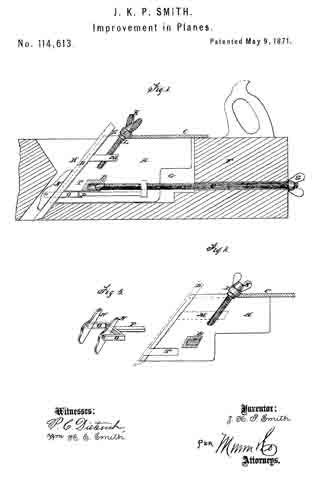
Figure 1 is a longitudinal sectional elevation of my improved plane. Fig. 2 is a longitudinal section through the casting. Fig. 3 is a perspective view of a part of the clamping apparatus.
Similar letters of reference indicate corresponding parts.
A represents two vertical plates, joined by the cross-bar B and the top plate, C. Said plates have the front ends inclined in the same angle the plane-bit D is to be set in, and these ends have rabbets E for the plane-bit to rest in at each edge. This casting is a little wider than the plane-bit, and not quite as deep as the height of the wood stock F. It is let into a deep recess, G, behind the throat H, so that the top plate, which is wider than the recess, will rest at the projecting edges on the top of the stock F to be screwed down to it.
The end of plate C toward the plane-bit has a boss, I, perpendicular to the line of the plane-bit, for the support of the adjusting-screw K, for setting the bit, which screw is fitted in a hole through said boss, and provided with a collar, L, which, together with the head of said screw, prevents end movement. This screw works in a stud, M, projecting from the back of the plane-bit, for adjusting the latter.
N represents clamping-bars, pivoted to the prongs O of a yoke, P, at the insides of said arms near the ends, to be clamped against the front side of the plane-bit for pressing the latter against the ends of plates by the clamping-screw Q, screwing through the end R of said yoke, and extending rearward through the end of the planestock, where it is provided with a thumb-bit, S, for turning the screw. The said arms O work in slots T in the ends ot’ the plates A, and extend beyond the edges ofthe plane-bit for holding the bars N against the front side. The said bars are pivoted to the arms for allowing them to bear fair upon the plane-bit.
The inner end of the screw has a bearing in the cross-bar B, which has a socket, T, made for it. The said screw, being turned by the thumb-bit S to draw the yoke toward the rear, will clamp the plane-bit firmly against the ends of the plates, as clearly shown, and being turned the other way releases it.
To remove the plane-bit the clamp is released as much as it can readily be, and the bit forced down by screw K till stud M is disengaged; then the upper end of the bit is tilted forward to clear the stud M from the lower end of screw K, when the bit may be lifted out.
Having thus described my invention, I claim as new and desire to secure by Letters Patent —
1. The combination, with the plane-bit and the wood stock, of the casting A B C, yoke P, clamps N, and clamping-screw Q, all substantially as specified.
2. The combination, with the above, of the adjusting-screw K, substantially as specified.
JAMES K. P. SMITH.
Witiiesses:
HENRY B. DIBBLE,
JNO. W. SULLIVAN.