
| PLEASE NOTE: The images presented on this page are of low resolution and, as a result, will not print out very well. If you wish to have higher resolution files then you may purchase them for only $2.95 per patent by using the "Buy Now" button below. All purchases are via PayPal. These files have all been cleaned up and digitally enhanced and are therefore suitable for printing, publication or framing. Each zip package contains all the images below (some packages may contain more), and purchased files can be downloaded immediately. |


UNITED STATES PATENT OFFICE.
_________________
THEODORE G. SELLECK, OF CHICAGO, ILLINOIS, ASSIGNOR OF ONE-HALF TO JOHN L. DEPPEN, OF CHICAGO, ILLINOIS.
BENCH-PLANE.
_________________
1,157,594. Specification of Letters Patent. Patented Oct. 19, 1915.
Application filed January 26, 1914. Serial No. 814,479. Renewed March 17, 1915. Serial No. 15,055.
_________________
To all whom it may concern:
Be it known that I, THEODORE G. SELLECK, a citizen of the United States, residing at Chicago, in the county of Cook and State of Illinois, have invented certain new and useful Improvements in Bench-Planes, of which the following is a specification.
This invention relates to bench-planes, and its object is to provide a structure which permits the bit to be quickly and easily removed for sharpening, without disturbing the adjusting means thereof.
The invention also has for its object to provide novel and improved means for adjusting the bit.
Other objects and advantages of the invention will be pointed out in the detailed description appearing hereinafter, and in order that the same may be better understood, reference is had to the accompanying drawings, in which —
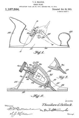
Figure 1 is a side elevation of a bench plane constructed in accordance with the present invention; Fig. 2 is a longitudinal section on the line 2–2 of Fig. 4; Fig. 3 is a sectional detail showing a slightly modified form of bit; Fig. 4 is a section on the line 4-4 of Fig. 1; Fig. 5 is a section on the line 5–5 of Fig. 1, and Fig. 6 is a section on the line 6–6 of Fig. 4.
Referring specifically to the drawing the stock of the plane is of conventional form, the same comprising a sole 10, side or check-pieces 11, a rear hand grip 12 and a forward knob 13. The sole has a slot 14 through which the bit 15 protrudes.
The bit 15 is carried by a member 16 which is pivotally mounted between the side pieces 11 in a manner to be presently described. By thus pivoting the bit carrier the same may be rotated to take the bit out of the slot 14 as shown by dotted lines in Fig. 1, the bit then pointing upward and being free of the side pieces, in which position it is readily accessible for the purpose of removal. The axis of rotation of the bit carrier is transverse of the stock. The bit carrier 16 tapers toward the end which carries the bit 15, said end having a dovetailed transverse groove 17 in which the bit seats and is held, the rear portion of the bit being shaped to fit in the groove.
The following clamping means for the bit 15 is provided: In the under side of the bit carrier 16 is a threaded aperture to receive a screw 18. This aperture is so located that it intersects the inner end of the groove 17, thus allowing a portion of the back of the bit to extend into the aperture, at the place where the beveled side of the screw head 19 seats, the aperture being countersunlr to accommodate said screw head. By working the screw inward, the beveled side of the head is forced against the back of the bit, and the bit is forced forward to a rigid seat in the groove. The bit can be readily removed by sliding it along the groove, after backing the screw.
Fig. 3 shows a slightly modified form of bit, its inner end having a shoulder 20 which abuts against the end of the bit carrier 16. The bit carrier 16 is a hollow casting having side openings 21. The sides of the bit carrier are flat and parallel, and its width is such that it has a small amount of side play between the side pieces 11. The bit carrier is carried by a yoke, the side arms 22 of which latter seat in longitudinal grooves 23 in the sides of the bit carrier. The connecting bar 24 of the yoke extends across and in spaced relation with the rear end of the bit carrier, or that end which is opposite the end carrying the bit 15. The bar 24 has, midway between its ends, an aperture in which is held an adjusting screw 25 which is threaded through a block 26 carried by the bit carrier, the latter having an aperture 27 to accommodate the inner end of the screw. The screw is held against travel in the direction of its length by its head 27a and a collar or washer 28 located, respectively, on opposite sides of the bar 24. Thus, it will be seen that when the screw is operated, the bit carrier is moved baclr and forth between the arms 22 to regulate the degree of protrusion of the bit through the slot 14.
The yoke is pivoted to the side pieces 11, which provides the hereinbefore described pivotal support for the bit carrier 16. The pivotal connection is made by pivot screws 29 passing through the side pieces and threaded into the arms 22 of the yoke. The heads 30 of the pivot screws are countersunk in the side pieces, and their shanks are devoid of threads where they pass through the side pieces, which enables the bit carrier to be swung without causing the pivot screws to tighten up.
The block 26 seats against the rear end of the bit carrier 16 between outstanding spaced ribs 31 and 32 on the latter, and it is pivoted at one end so that it may swing outward from the end of the bit carrier. The pivotal connection is made by a pin 33 passing through the block and held at its ends in the ribs 31 and 32. The free end of the block is shaped to form a half nut, the thread 34 of which fits in the groove of a worm 35 seating in a recess in the end of the bit carrier, and mounted on a pivot screw 36 carried by the latter. The worm carries a small projecting finger-piece 37 for operating the same.
Upon turning the worm 35 in one direction, by means of the finger-piece 37, the block 26 swings outward from the bit carrier 16, as shown by dotted lines in Fig. 4, and it is swung back toward the bit carrier upon turning the worm in the opposite direction. This movement of the block reults in giving the bit carrier a sidewise tilt to line up the slot 14.
In order to prevent the bit carrier 16 from rocking when the tool is in use, a stout spring latch 38 is provided, the same being secured to the sole 10 and having its free end offset and shaped to snap under the bar 24. When the latch is in holding position, the rear end of the bit carrier cannot swing downward, and it is prevented from swinging upward by the bit 15 engaging the rear wall of the slot 14. Upon disengaging the latch from the yoke bar, the bit carrier may be swung to the dotted line position shown in Fig. 1, for the purpose stated hereinbefore.
I claim:
1. A bench-plane comprising a stock having side-pieces, a yoke pivotally mounted between the side-pieces, a bit carrier carried by the yoke and adjustable in the direction of its length, and means for locking the yoke.
2. A bench-plane comprising a stock having side-pieces, a yoke pivotally mounted between the side-pieces, a bit carrier carried by the yoke, an adjusting screw carried by the yoke and having a threaded engagement with the bit carrier, and means for locking the yoke.
3. A bench-plane comprising a stock having side-pieces, a yoke pivotally mounted between the side-pieces, a bit carrier having longitudinal side grooves, in which the yoke arms seat, means for adjusting the bit carrier in the direction of its length, and means for locking the yoke.
4. A bench-plane comprising a stock having side-pieces, a yoke pivotally mounted between the side-pieces, a bit carrier carried by the yoke and adjustable sidewise and in the direction of its length, and means for locking the yoke.
5. A bench-plane comprising a stock having side-pieces, a yoke pivotally mounted between the side-pieces, a bit carrier carried by the yoke, a pivoted member carried by the bit carrier, an adjusting screw carried by the yoke and having a threaded engagement with the pivoted member, a worm carried by the bit carrier and having a threaded engagement with the free end of the pivoted member, and means for locking the yoke.
6. A bench-plane comprising a stock, a bit carrier, a support for the bit carrier carried by the stock, a pivoted member carried by the bit carrier, an adjusting screw carried by the support and having a threaded engagement with the pivoted member, and a worm carried by the bit carrier, and having a threaded engagement with the free end of the pivoted member.
In testimonv whereof I affix my signature in presence of two witnesses.
THEODORE G. SELLECK.
Witnesses:
S. J. LEHRER,
H. W. BATCHELOR.
Copies of this patent may be obtained for five cents each, by addressing the “Commissioner of Patents, Washington, D. C.”
_________________