| PLEASE NOTE: The images presented on this page are of low resolution and, as a result, will not print out very well. If you wish to have higher resolution files then you may purchase them for only $2.95 per patent by using the "Buy Now" button below. All purchases are via PayPal. These files have all been cleaned up and digitally enhanced and are therefore suitable for printing, publication or framing. Each zip package contains all the images below (some packages may contain more), and purchased files can be downloaded immediately. |
UNITED STATES PATENT OFFICE.
_________________
EDMUND A. SCHADE, OF NEW BRITAIN, CONNECTICUT, ASSIGNOR TO THE STANLEY RULE &
LEVEL COMPANY, OF NEW BRITAIN, CONNECTICUT, A CORPORATION OF CONNECTICUT.
PLANE.
_________________
1,164,615. Specification of Letters Patent. Patented Dec. 14, 1915.
Application filed March 26, 1915. Serial No. 17,143.
_________________
To all whom it may concern:
Be it known that I, EDMUND A. SCHADE, a citizen of the United States, residing at New Britain, county of Hartford, in the State of Connecticut, have invented certain new and useful Improvements in Planes, of which the following is a full, clear, and exact description.
This invention relates to metal tool bodies and the process of forming the same. The tool body so formed is designed to provide lightness as far as weight is concerned, with effectiveness of structure and strength to resist load strains under practical working conditions. The parts are so combined and connected that there will be practically no distortion due to load strain, or at least so that distortion is minimized. The tool body so formed is light yet substantial and combines with this desirable quality the further desideratum of rigidity.
For the purpose of illustrating and describing a specific embodiment thereof, I have selected a metal plane, the specific construction of which is described in the following detailed specification, taken in connection with the accompanying drawings which illustrate a preferable embodiment of such a plane body.
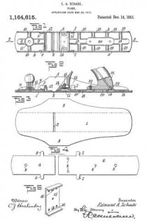
In these drawings, — Figure 1 is a plan view of the plane body, parts of the plane being omitted. Fig. 2 is a longitudinal vertical section on the line 2–2 of Fig. 1, portions of the operative parts of the plane being shown to illustrate the purpose of the body structure. Fig. 3 is a plan view of a metal blank from which the outer shell or case of the body is formed. Fig. 4 illustrates the metal blanks from which the inner face of the body is formed, these blanks being subsequently treated to provide the strengthening corrugations and tool seats. Fig. 5 is a detail of construction.
Referring to the drawings by numerals, 1 designates the base or shoe portion of the outer shell slotted at 2 to provide the usual cutter throat. This base is provided with side walls or flanges giving the shell or shoe a channel formation. Preferably this outer shell of the plane body is formed of sheet metal stock which may be bent up from a single blank, such as shown in Fig. 3, to form the side walls or flanges 3 and the base 1. This outer shell by itself will hardly be substantial enough to stand the load strain of actual working conditions. I have provided an inner bracing means for this outer shell which bracing means is designed to carry the operating parts of the tool and take a large portion of the load strain from the outer shell. I preferably form this bracing means also from sheet metal stock.
In Fig. 4, 4 designates a metal blank having laterally extending ears 5, and 6 designates a metal blank of the same width but greater length having similar laterally extending ears 7. The two blanks, before the bending operation about to be described, are each provided with threaded bores 3 therein to receive screws from the handle and other parts of the tool. The first blank 4 is of a width to fit between the side walls 3 of the outer shoe. It is treated in a press or other machine to form longitudinal strengthening corrugations 9 therein and preferably also laterally extending corrugations 10, the blank at the intersection of these corrugations being formed with a raised seat 11 for the hand-knob of the plane to rest upon. At the rear end of the longitudinal corrugation 9 the blank is bent laterally to form an upwardly extending bridge 12, the ears 5 being turned inwardly to rest against the side walls or flanges 3 of the outer shell. It will be understood that the side edges of the formed blank will have a snug fit within the side flanges 3 of the outer shell, and that the ears 5 and the edges of the bridge 12 will likewise abut thereagainst at a point substantially above the base 1. The formed blank 4 will be positioned forwardly of the throat 2 in the outer shell. The blank 6, which is designed to carry the cutter, handle, etc, is positioned to the rear of this cutter throat slot. Its forward edge is struck up to form a raised seat or bridge 13, which may constitute a seat for the plane-frog 14; (Fig. 2), this frog having attaching screws 15 which extend through the apertures 8 and into the threaded bores 16 in a strengthening metal piece or blanking 17, which will be positioned under the seat or bridge 13 and above the upper face of the base 1 of the outer shell. This blanking 17 is preferably previously secured to the seat in a suitable manner, as by riveting, although the welding process hereinafter described may also be employed. The ears 7 of the blank 6 are bent upwardly to abut against the sides 3 of the outer shell at points substantially at the base of said shell. The blank is also treated in a press or other instrumentality to provide it with longitudinally extending corrugations 18 and also preferably with a plurality of transversely extending corrugations 19. Intermediate its ends the corrugation 18 is enlarged and elevated to form the raised seat 20 to which the tool handle 21 may be attached by screws 22 taking into the threaded bores 8 previously formed in the blank. When these formed blanks have been assembled in their proper positions upon the upper face of the base of the outer shell, they are preferably secured thereto and rigidly united therewith by fusing the parts together. The method I preferably employ is known as “spot welding.” This spot welding operation preferably takes place about the outer edges of the formed plates so that these formed plates will be fused to the outer shell at points along the lines of the edges of the plates so as to make the outer shell stiii at the point where the side flanges are bent upwardly therefrom, which would otherwise make the body weak at that point. The ears 5 and 7 are also welded to the side walls and with the raised bridge edges, seats, etc., strengthen the outer shell at points above the bend of the side walls, the fusion of the metal taking place therefore, at both sides of the bend and the inner plates. The spot welding may take place both at the outer edges of the plates 4 and 6 and inwardly of said edges and between the edges and the corrugations. These corrugations materially strengthen the base against distortion through working strain, and as the seats for the tool operating parts are raised, these parts do not contact with the base. Consequently the operating load strain is largely taken by the corrugations which, together vvith the bridges, prevent distortion of the base.
What I claim therefore and desire to secure by Letters Patent is:
1. A plane having a tool body of deformable metal, comprising an outer shell having a base and integral upwardly extending side walls, and an inner plate permanently secured to said ba.se and to said upwardly extending side walls, said inner plate having intersecting longitudinally and laterally extending raised strengthening corrugations formed therein bracing the outer shell against longitudinal and lateral strains, and forming a handle support and securing means.
2. A tool body of deformable metal comprising an outer shell having a base and integral upwardly extending side walls and an inner plate permanently secured to said base and to said upwardly extending side walls, said inner plate having intersecting longitudinally and laterally extending raised strengthening corrugations formed therein and said corrugations being broadened at their intersection to provide a longitudinally and laterally braced seat for a tool operating part, raised above the plane of the base whereby communication of deforming strains from such tool operating part to said base is prevented.
EDMUND A. SCHADE.
Witnesses:
ALBERT L. WIARD,
W. J. WORAM.
Copies of this patent may be obtained for five cents each, by addressing the “Commissioner of Patents, Washington, D. C.”
_________________


