
| PLEASE NOTE: The images presented on this page are of low resolution and, as a result, will not print out very well. If you wish to have higher resolution files then you may purchase them for only $2.95 per patent by using the "Buy Now" button below. All purchases are via PayPal. These files have all been cleaned up and digitally enhanced and are therefore suitable for printing, publication or framing. Each zip package contains all the images below (some packages may contain more), and purchased files can be downloaded immediately. |

UNITED STATES PATENT OFFICE.
_________________
JOHN F. THUNELL, OF SALT LAKE CITY, UTAH.
HAND-PLANE.
_________________
1,171,076. Specification of Letters Patent. Patented Feb. 8, 1916.
Application filed November 17, 1914. Serial No. 872,608.
_________________
To all whom it may concern:
Be it known that I, JOHN F. THUNELL, a citizen of the United States, residing at Salt Lake City, in the county of Salt Lake and State of Utah, have invented certain new and useful improvements in Hand-Planes, of which the following is a specification.
This invention relates to bit adjustments for hand planes, and the object of the invention is to provide novel and peculiar means for adjusting hand plane bits which shall be of simple construction, conveniently assembled, and accurately manipulated.
The object of the invention is to provide novel and peculiar means for adjusting and fixing the plane bit, and special means for hanging and adjusting the base or surface bearing plates of the plane.
A further object of the invention is to provide in the bit adjustment, convenient, simple, durable and effective means for giving the bit minute, accurate and positive adjustment independent of the base plate adjustment.
A still further object of the invention is to provide a pair of surface or runner plates, and a screw rod hinged to each plate, and a pair of adjusting and locking nuts for each rod, the adjusting nuts being held within the plane stock.
Other objects, advantages and improved results will be found in the practical application of the plane.
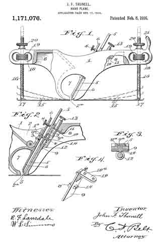
In the accompanying drawings forming part of this application: Figure 1 is a side elevation showing in dotted lines the various positions of the base plates. Fig. 2 is a sectional view of the bit device. Fig. 3 is a detail cross section on the dotted lines x–x, Fig. 2. Fig. 4 is a detail perspective view of the bit bracket.
The same reference characters denote the same parts throughout the several views of the drawings.
The plane stock or body 1, has a concavity 2 in its top in which set-screws 3 and 4 are operated in connection with a bit 5 and its keeper 6. The screw 3 works through a hinged carrier 1a, to connect the keeper therewith, and the thumb screw 4 works through the upper end of the keeper as usual. A transverse opening 7 is made through the stock under the ccncavity 2, and a bit slot 2a is made through the bottom wall of the opening 7. The under side of the stock is cut out at 8, for the purpose of reducing the weight of the plane, and for the purpose of housing the bit adjusting device. The bit adjusting device comprises a bracket the long plate 9 of which has a lug 8a working in the bit slots 9a covered by the plate 9, and the short plate 10 of the bracket is secured to the inclined wall 11 of the cut out portion 8 of the stock. The plate 10 forms a collar 10a in which a worm screw 12 is operated. Said screw having a stem extending through the top of the stock on an incline and parallel with the bit, and the stem is provided with a thumb head 13 for operating the screw. The plate 9 is provided with a follower projection 14 meshing with the screw 12, and the plate 9 has a forked end for the plate 10.
The pair of flexible runners 15, have their inner ends secured flush with the bit slot 2a, and the outer end of each plate is curved upwardly. A screw rod 16 is hinged or pivoted at 17 adjacent to the said curved end of each plate, and said rods extend through the ends of the stock 1. The ends of the stock are provided with transverse slots 18 and hold thumb nuts 19 for operating the rods 16, and set nuts 20 are provided for holding the rods in set position. One end of the stock is provided with a hand abutment 21 projecting above the nut 20 at this end of the stock, and thereby prevents the hand from interfering with the nut and rod.
It will be observed that the follower answers two purposes, it forms the connection between the bit and the bracket, and it also affords means for imparting to the bit the movement of the worm screw.
Having thus described my invention what I claim as new and desire to secure by Letters Patent is :–
In a bit plane, a plane throat the under wall of which has a slot lengthwise thereof, a plate of larger area than the slot and slidable on the under face of said wall opposite the slot, a lug on the upper face of the plate and projecting through the slot into engagement with the bit, a lug on the lower face of the plate, and a screw spaced apart from said wall equal to the thickness of the plate and engaging the plate and the lower lug to keep the upper lug in engagement with the bit for longitudinal adjustment by the screw.
In witness whereof I hereunto set my hand in the presence of two witnesses.
JOHN F. THUNELL.
Witnesses:
ISAAC P. THUNELL,
MATIE S. ASHTON.
Copies of this patent may be obtained for five cents each, by addressing the “Commissioner of Patents, Washington, D. C.”
_________________