

| PLEASE NOTE: The images presented on this page are of low resolution and, as a result, will not print out very well. If you wish to have higher resolution files then you may purchase them for only $2.95 per patent by using the "Buy Now" button below. All purchases are via PayPal. These files have all been cleaned up and digitally enhanced and are therefore suitable for printing, publication or framing. Each zip package contains all the images below (some packages may contain more), and purchased files can be downloaded immediately. |
UNITED STATES PATENT OFFICE.
_________________
HENRY N. FREDERICK, OF HANCOCK, NEW YORK.
IMPROVEMENT IN CARPENTERS’ PLANES.
_________________
Specification forming part of Letters Patent No. 119,133, dated September 19, 1871.
_________________
To all whom it may concern:
Be it known that I, HENRY N. FREDERICK, of Hancock, in the county of Delaware and State of New York, have invented a new and Improved Carpenters’ Plane; and I do hereby declare that the following is a full, clear, and exact description thereof, which will enable others skilled in the art to make and use the same, reference being had to the accompanying drawing forming part of this specification.
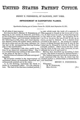
Figure 1 represents a side view, partly in section, of my improved carpenters’ plane. Fig. 2 is a vertical transverse section of the same taken on the plane of the line c c, Fig. 1.
Similar letters of reference indicate corresponding parts.
My invention consists in the improvement of carpenters’ planes, as hereinafter described and subsequently pointed out in the claim.
A, in the drawing, represents the block or frame of a carpenter’s plane. B is the planing-iron. The face of the iron has a toothed portion, a, into which mesh the teeth of a segment, C. This segment is formed at the lower end of a lever, D, that turns on a pin, b, whose bearings are in the sides of the plane. By swinging the lever D on its pivot, the iron B will be set up or down, as may be desired. E is a slotted lever pivoted to the plane A. By means of a thumb-screw, d, fitting through the lever E into D, the latter can be clamped to lock the iron B in any suitable position. Other means for thus securing the lever D and iron, may, however, be substituted for lever E and screw d.
Having thus described my invention, I claim as new, and desire to secure by Letters Patent —
The toothed segment C pivoted to the plane A, and combined with the iron B, which has the toothed portion a, substantially as herein shown and described.
HENRY N. FREDERICK.
Witnesses:
M. D. WHEELER,
MILO SCUTT.