
| PLEASE NOTE: The images presented on this page are of low resolution and, as a result, will not print out very well. If you wish to have higher resolution files then you may purchase them for only $2.95 per patent by using the "Buy Now" button below. All purchases are via PayPal. These files have all been cleaned up and digitally enhanced and are therefore suitable for printing, publication or framing. Each zip package contains all the images below (some packages may contain more), and purchased files can be downloaded immediately. |
UNITED STATES PATENT OFFICE.
_________________
SIDNEY W. PALMER AND ELLIOT G. STORKE, OF AUBURN, NEW YORK,
ASSIGNORS TO WILLIAM J. MOSES, OF SAME PLACE.
IMPROVEMENT IN BENCH-PLANES.
_________________
Specification forming part of Letters Patent No. 121,406, dated November 28, 1871.
_________________
To all whom it may concern:
Be it known that we, SIDNEY W. PALMER and ELLIOT G. STORKE, of Auburn, in the county of Cayuga and in the State of New York, have invented certain new and useful Improvements in Bench-Planes; and do hereby declare that the following is a full, clear, and exact description thereof, reference being had to the accompanying drawing making a part of this specification, in which —
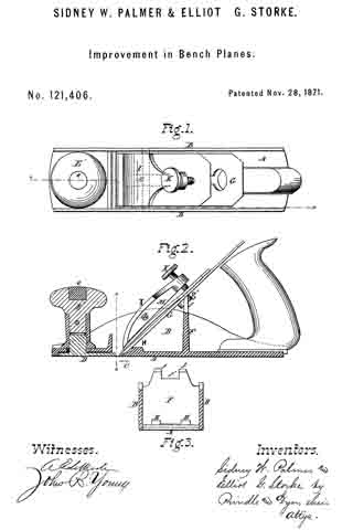
Figure 1 is a plan view of our improved plane. Fig. 2 is a vertical longitudinal section of the same on the line x x of Fig. 1, and Fig. 3 is a vertical cross-section on the line z z of Fig. 2.
Letters of like name and kind refer to like parts in each of the figures.
Our invention is an improvement in that class of bench-planes having metallic stocks; and it consists, principally, in the employment upon the lower side of the pivoted cap of a central rib extending the whole length of said cap, substantially as and for the purposes hereinafter shown. It consists, further, in a cap pivoted at or near its center transversely to the stock, substantially as and for the purpose hereinafter set forth. It consists, further, in the construction of the bearings upon which the heel of the bit rests, substantially as and for the purpose hereinafter specified. It consists, further, in the relative arrangement of the bearings for the heel of the bit with those employed for the body of the same, substantially as hereinafter shown and described. It consists, finally, in the combination of the above-named bearings with the center pivoted cap, substantially as and for the purpose hereinafter set forth.
In the annexed drawing, A represents the name or stock, provided at either side with an upward-projecting flange, B, for inclosing and supporting the cap, and having near its forward end a suitable transverse opening, C, ibr the reception ef the lower or cutting end of the bit, which opening is made variable in width by means of a plate, D, that corresponds in width to the length thereof, and sliding longitudinally within a recess formed in the face of the stock, is secured in position, when adjusted, by means of a screw which projects upward through a longitudinal slot within said stock, and is provided upon its upper end with a nut, E. Secured within or upon the upper end of the nut E is a wooden knob, E’, within which is in turn secured a metallic stud or start-pin, e, the upper end of which is considerably enlarged so as to enable it to resist a blow from a hammer when it is desired to start back the bit. Projecting vertically upward from the stock A, near its longitudinal center, is a diaphragm, F, which from the upper edges of the flanges B curves inward and upward and terminates in two lugs, f separated by means of a notch, f’, upon which, when in position, the body of the bit G rests. The notch f’ is deepened sufficiently to permit of the passage of the screw g’ of the cap G’, by which means less space vertically is required for the removal of the bit than would otherwise be the case. At a short distance in rear of the opening C are placed two other lugs, H, which correspond in width and relative transverse position with those above described, and furnish a bearing for the heel of the bit. It will be readily seen that being supported at but two points midway between its transverse center and edges the bit must invariably have a firm bearing, however unequal its thickness or uneven its heel. Pivoted to and within the upper edges of the flanges B is a cap, I, having the usual curved form and provided at and through its upper and rear end with a suitable set-screw, K. Instead of the usual transverse rib for the reception of the pivot-rod L, a longitudinal rib, M, extends through the center of the cap, and not only contains said rod, but also strengthens said cap and enables other portions ofthe same to be made much lighter than would otherwise be practicable.
By making the opening through the rib M for the passage of the pivotal rod L slightly larger than said rod the cap will be enabled to adjust itself vertically to the bit, however unequal in thickness the same may be at its lower end. Another advantage possessed by the longitudinal rib is that it not only offers no obstruction to the center of the bit, but rather furnishes a guide for the same, while in caps where the transverse rib is employed great care is required in inserting the bit to avoid hitting said rib with the same and injuring its cutting-edge.
Having thus fully set forth the nature and merits of our invention, what we claim as new is —
1. In metallic bench or other planes a pivoted cap, provided upon its lower side with a central longitudinal rib, substantially as and for the purpose specified.
2. The cap I, pivoted loosely at or near its transverse center, substantially as and for the purpose shown.
3. The arrangement of the lugs or bearings H upon the stock A, substantially as shown and for the purpose described.
4. The stock A, provided with the bearings H and f arranged substantially as and for the purpose set forth.
5. In combination with the bearings H and f and a suitable bit, the cap I, pivoted at or near its transverse center, substantially as and for the purposes specified.
In testimony that we claim the foregoing we have hereunto set our hands this 10th day of August, 1871.
ELLIOT G. STORKE.
SIDNEY W. PALMER.
Witnesses:
HORACE T. COOK,
JAY E. STORKE.