
| PLEASE NOTE: The images presented on this page are of low resolution and, as a result, will not print out very well. If you wish to have higher resolution files then you may purchase them for only $2.95 per patent by using the "Buy Now" button below. All purchases are via PayPal. These files have all been cleaned up and digitally enhanced and are therefore suitable for printing, publication or framing. Each zip package contains all the images below (some packages may contain more), and purchased files can be downloaded immediately. |
UNITED STATES PATENT OFFICE.
_________________
ORRIL R. CHAPLIN, OF BOSTON, ASSIGNOR TO HIMSELF AND CHARLES H.
BALLARD, OF WORCESTER, MASSACHUSETTS.
IMPROVEMENT IN CARPENTERS’ PLANES.
_________________
Specification forming part of Letters Patent No. 126,519, dated May 7, 1872.
_________________
To all whom it may concern:
I, ORRIL R. CHAPLIN, of Boston, in the county of Suffolk and State of Massachusetts, have invented certain new and useful Improvements in Joiners’ and Carpenters’ Planes, of which the following, taken in connection with the accompanying drawing, is a specification:
My invention relates, in the first place, to the means employed to secure the cutter to the stock and to adjust the same when so secured, and is more particularly applicable to planes the stocks of which are made wholly or in part of metal; and it consists in the employment of a saddle or rest-plate which forms the bearing for the upper portion of the cutter, and to which it is secured by the clamping device, said saddle being secured to the plane-stock by a single screw passing through a slot in the saddle and so adjusted that the saddle may be moved endwise to adjust the “tooth” of the cutter, as will be described. It also consists in the use of a screw cam-lever, the thread of which works in a half-nut formed upon or secured to the under side of the saddle or cutter for the purpose of adjusting the cutter to give the desired “tooth” to the same. It also consists in the use of a clamping-plate provided with a lug on either side thereof projecting downward, each terminating with a hook at its lower end, which engages with the under side of the saddle and acts as a fulcrum for the clamping-plate when the screw in its upper end is operated to bind the cutter, saddle, and clamping-plate together.
My invention relates, in the second place, to the construction of the cutter and cap; and it consists in the use, as a substitute tor the ordinary cap now in general use on all plane-irons or cutters for dressing hard wood or cross-grained stock, of a short plate of metal secured loosely by its middle to the lower end of the clamping-plate by two or more rivets, said plate being so formed that it can only bear upon the cutter at its upper and lower edges, and the clamping-plate being so formed that it can bear upon said plate at or near its middle only in a line across its width, said plate being so secured to the clamp that it is susceptible of a slight rocking motion, so that it may accommodate itself to the surface of the cutter. By the use of this combined clamp-plate and cap, the lower edge of which is of the proper form and adjusted to the proper point to serve all the purposes of the common cap of a double plane-iron or cutter, I am enabled to use a plain cutter-iron without slots or holes of any kind, thus reducing the cost of the cutter, and also the weight of the plane.
My invention relates, in the third place, to the means employed to reduce the adhesion of the plane-stock to the material being dressed; and it consists in perforating the race of the plane-stock with a series of holes, thereby reducing the area of the stock exposed to atmospheric pressure.
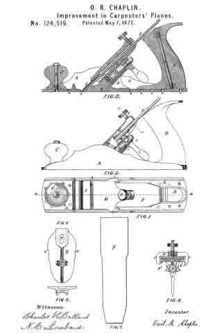
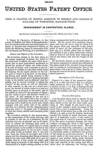
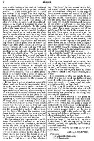
Figure 1 is a plan of my improved plane. Fig. 2 is a side elevation; Fig. 2, a longitudinal section on line x x on Fig. 1. Fig. 4 is a section on line z z on Fig. 2, looking toward the throat otf the plane. Figs. 5 and 6 are details of the saddle, and Fig. 7 is a plan of the cutter.
A is the plane-stock made of metal; B, the handle; and C, a knob on the forward end upon which to rest the left hand while operating it. The handle B and knob C are secured to the metallic stock by means of the screw-bolts a and b, respectively. Upon the upper side of the stock, just in the rear of the throat c, is cast a boss, D, sloping backward toward the handle at about the same angle that it is desirable to give to the cutter, to the upper side of which is secured the saddle E by the screw d passing through the slot e without bringing the head to bear upon the saddle so as to bind it to the stock. The saddle E is provided with a shoulder, e’, on either side, against which the lugs on the clamp, to be described, strike to determine the position of the clamp in an obvious manner. F is the cutter made of the form shown in Fig. 7, the upper or rear portion being made narrower than the cutting end to facilitate the application and removal of the clamp, and also to allow play for adjusting the cutting-edge square with the face of the stock at the throat if the cutter should not be ground perfectly square. G is the clamp, provided at about the middle of its length with two lugs, f f, (one on either side,) projecting downward and terminating in hooks f’ f” upon their inner faces, as shown in Fig. 4. The clamp G is also provided at its upper-end with a thumb-screw, H, by which it is secured in place, as will be presently explained. To the under side of the lower end of the clamp is riveted loosely the plate g, the lower end of the clamp being so formed as to rest upon the plate near its middle without touching at any other point, and the plate g being so fitted that it is susceptible of a slight rocking motion. This plate serves the purpose of the ordinary cap upon a double plane-iron or cutter, the clamp and this plate combined serving the double purpose of clamp and cap with less cost to manufacture, less trouble to adjust and less weight to handle than by the use of the old style double-iron. To the upper or rear end of the boss D is pivoted the lever I by means of the pin h. The hub of the lever I is partially surrounded by the segments of screw-threads s s, which work in the half-nut i upon the under side of the saddle E, and by a movement of the lever I to the right the cutter is forced outward, and if the lever be moved to the left the cutter will be drawn in in an obvious manner. The face of the plane-stock is perforated with a series of holes, as seen at n n n in Fig. 3, for the purpose of reducing the area exposed to the pressure of the atmosphere.
It has been a serious objection to metallic plane-stocks as heretofore constructed that, owing to the more nearly perfect surfaces of their faces, the pressure of the atmosphere upon their upper surfaces, when working upon stock planed to nearly the same level surface, causes an adhesion of the plane to the wood, which materially increases the labor of operating it, especially when using a jointer or large plane. This difliculty is not so serious with wooden plane-stocks, for the simple reason that they are seldom so true but that more or less air is between the plane-stock and the material being worked. By perforating the face of the plane the pressure is reduced just in proportion to the area removed by the perforations without injuring the face of the plane for any practical purpose.
The operation of my improvement is as follows: The saddle E is secured to the stock, as shown, by means of the screw d, the under side of the head being at such a point that when the saddle is brought to bear against it the top of the saddle shall be slightly below the inclined surface in the stock of the plane just in the rear of the throat, so as to insure a good bearing of the cutter at its extreme lower end to prevent. it from chattering. The lever I is then moved to the left, the cutter placed in position on the saddle, and the combined clamp and cap is slipped down over the cutter and saddle till the lugs f f come in contact with the shoulders e’ e’ upon the saddle. The plane is then taken in the left hand, with the thumb pressing upon the clamp to hold it in position, and the edge of the cutter is adjusted to the cap, when the thumb-screw H is operated, which forces the cutter down upon the upper end of the saddle, and, forcing the half-nut upon its under side down upon the screw-cam on the hub of the lever I and acting upon that as a fulcrum, lifts the lower end of the saddle hard against the head of the screw d, thus holding the saddle rigidly in its place, and as the lower end of the saddle is still slightly below the incline upon which the lower end of the cutter rests, the clamp, acting upon the hooks f’ f’ as a fulcrum, forces the lower end of the cutter firmly onto its seat.
To adjust the “tooth” of the cutter to take a thick chip, move the lever I to the right hand, and to take a thin chip move it to the left hand.
Having thus described my invention, I do not claim anything contained in the patent No. 64,790, granted to Nelson Palmer, May 14, 1867, for “Bench-Plane;” but
What I claim as new, and desire to secure hy Letters Patent of the United States, is as follows:
1. In combination with the saddle E, provided with the slot e and the half-nut i, and secured to the plane-stock by the screw d, I claim the cam-lever I, constructed and operating substantially as described.
2. The clamp G, provided with the lugs f fand hooks f’ f’, in combination with the saddle E, having the shoulders e’ e’ thereon, for determining the position of the clamp, substantially as described.
3. I do not claim broadly a cap-plate attached to the clamp instead of the bit or cutter, for I am aware that that has been done before; but I claim the cap-plate g, made of the form shown and secured by its middle to the clamp G, by being loosely riveted thereto in such a manner that it may be free to accommodate itself to the surface of the cutter upon which it bears at its upper and lower edges, substantially as described.
4. The combination and arrangement of the screw cam-lever I, the saddle E, the cutter F, the clamp G, and the cap-plate g, all constructed, applied, and operated substantially as herein described.
Executed at Boston this 14th day of February, 1871.
ORRIL R. CHAPLIN.
Witnesses:
CHARLES H. BALLARD,
N. C. LOMBARD.