
| PLEASE NOTE: The images presented on this page are of low resolution and, as a result, will not print out very well. If you wish to have higher resolution files then you may purchase them for only $2.95 per patent by using the "Buy Now" button below. All purchases are via PayPal. These files have all been cleaned up and digitally enhanced and are therefore suitable for printing, publication or framing. Each zip package contains all the images below (some packages may contain more), and purchased files can be downloaded immediately. |
UNITED STATES PATENT OFFICE.
_________________
JOHN BROOKS, OF BOSTON, MASSACHUSETTS.
IMPROVEMENT IN BENCH-PLANES.
_________________
Specification forming part of Letters Patent No. 127,842, dated May 28, 1872.
_________________
To all whom it may concern:
Be it known that I, JOHN BROOKS, of Boston, in the county of Suffolk and State of Massachusetts, have invented an Improved Bench-Plane; and I do hereby declare that the following, taken in connection with the drawing which accompanies and forms part of this Specification, is a description of my invention sufficient to enable those skilled in the art to practice it.
My invention relates to the construction of common bench-planes for cabinet and joiners’ work; and the object of the invention is to enable a workman to plane up into angles made by tenons, shoulders, and other projections in wood-work, into which angles the bits or irons of common planes cannot reach, being kept therefrom by the stock in which the plane-bit is held. In my invention I make a suitable plane-stock, with an upright or wall upon one side, (against which upright or wall the bit may be held,) but with no bit-inclosing flange, upright, or wall upon the opposite side to support the bit, the stock or plate being slotted to form the throat for the edge of the bit, and the slot extending out through the plate at one end, the bit being set so that its side edge (on one side) is in the plane of the side or edge of the plane-stock, the corner of the cutting-edge being at the end ofthe open throat or mouth. The plane bit or iron being clamped in position, it will be obvious that its edge will reach into any angle formed by a projection standing at a right angle to the general surface upon which the plane acts. It is in this construction that the invention consists.
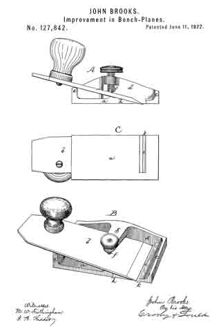
The drawing represents a plane embodying the invention.
A shows the side elevation of the plane; B, a perspective view of it; C, a bottom view of it.
a denotes a plate for supporting the bit b, this plate having a vertical flange, c, at its front end for imparting rigidity to the adjacent portion of the plate, an upright or wall, d, at one side, and a vertical flange, e, at its rear end, this latter supporting the rear part of the bit in proper inclined position. The bit is held down by a screw, f, which works in a nut-thread in the end of an arm, g, extending from the upright d. The front end of the bit is supported upon a bed or incline, h, and its cutting-edge extends down through and is adjusted with respect to the throat i. This throat is a slot cut through from one side, or opening out to the side, as seen in the drawing. The mouth or open end It of the slot is in a plane with the plain side or edge of the stock, and the edge of the bit is brought out to this edge and mouth.
It will be obvious that this construction enables the plane to cut to the extreme edge of the bit, or up to any angle made by a piece standing right angular to the general surface upon which the plane is at work.
In small work necessity for the use of such a tool constantly occurs, and this plane effects great saving in time and enables better work to be done than can be edected with the common plane.
I claim —
A bench-plane constructed substantially as shown and described.
Executed this 19th day of October, A. D. 1871.
JOHN BROOKS.
Witnesses:
FRANCIS GOULD,
M. W. FROTHINGHAM.