
| PLEASE NOTE: The images presented on this page are of low resolution and, as a result, will not print out very well. If you wish to have higher resolution files then you may purchase them for only $2.95 per patent by using the "Buy Now" button below. All purchases are via PayPal. These files have all been cleaned up and digitally enhanced and are therefore suitable for printing, publication or framing. Each zip package contains all the images below (some packages may contain more), and purchased files can be downloaded immediately. |
UNITED STATES PATENT OFFICE.
_________________
CHARLES E. MARSHALL, OF BOSTON, MASSACHUSETTS.
IMPROVEMENT IN MATCH-PLANES.
_________________
Specification forming part of Letters Patent No. 131,959, dated October 8, 1872.
_________________
To all whom it may concern:
Be it known that I, CHARLES E. MARSHALL, of Boston, in the county of Suffolk, in the State of Massachusetts, have invented certain Improvements in Match-Planes; and do hereby declare that the following description, taken in connection with the accompanying drawing, hereinafter referred to, forms a full and exact specification of the same, wherein I have set forth the nature of my said improvement, by which my invention may be distinguished from others of a similar class, together with such parts as I claim and desire to secure by Letters Patent.
My invention relates to that class of wood-working implements made use of for cutting grooves and tongues, commonly known as matching-planes; and the nature thereof consists in certain modifications and improvements in the details of the construction of the same, hereinafter described and shown.
In the accompanying plate of drawing, which illustrates my invention and forms a part of the specification thereof, corresponding parts are illustrated by similar letters.
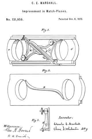
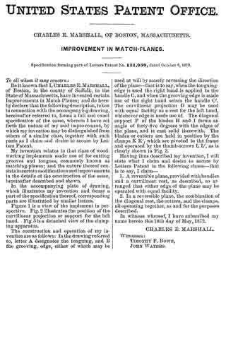
Figure 1 is a view of the implement in perspective. Fig. 2 illustrates the position of the curvilinear projection or support for the left hand. Fig.3 is a detached view of the clamping apparatus.
The construction and operation of my invention are as follows: In the drawing referred to, letter A designates the tonguing, and B the grooving, edge, either of which may be used at will by merely reversing the direction of the plane — that is to say, when the tonguing-edge is used the right hand is applied to the handle C, and when the grooving-edge is made use of the right hand seizes the handle C’. The curvilinear projection D may be used with equal facility as a rest for the left hand, whichever edge is made use of. The diagonal support F of the blades H and I forms an angle of forty-five degrees with the edges of the plane, and is cast solid therewith. The blades or cutters are held in position by the clamps K K’, which are pivoted to the frame and operated by the thumb-screws L L’, as is clearly shown in Fig. 3.
Having thus described my invention, I will state what I claim and desire to secure by Letters Patent in the following clause — that is to say, I claim —
1. A reversible plane, provided with handles and a curvilinear rest, as described, so arranged that either edge of the plane may be operated with equal facility.
2. In a reversible plane, the combination of the diagonal rest, the cutters, and the clamps, all operating together, as and for the purposes described.
In witness whereof, I have subscribed my name hereto this 18th day of May, 1872.
CHARLES E. MARSHALL.
Witnesses;
TIMOTHY F. BOWE,
JOHN WATERS.