
| PLEASE NOTE: The images presented on this page are of low resolution and, as a result, will not print out very well. If you wish to have higher resolution files then you may purchase them for only $2.95 per patent by using the "Buy Now" button below. All purchases are via PayPal. These files have all been cleaned up and digitally enhanced and are therefore suitable for printing, publication or framing. Each zip package contains all the images below (some packages may contain more), and purchased files can be downloaded immediately. |
UNITED STATES PATENT OFFICE.
_________________
LEONARD BAILEY, OF WINCHESTER, MASSACHUSETTS.
PLANE-SCRAPER.
_________________
Specification of Letters Patent No. 13,381, dated August 7, 1855.
_________________
To all whom it may concern:
Be it known that I, LEONARD BAILEY, of Winchester, in the county of Middlesex and State of Massachusetts, have invented an Improved Plane-Scraper; and I do hereby declare that the same is fully described and represented in the following specification and the accompanying drawings, letters, figures, and references thereof.
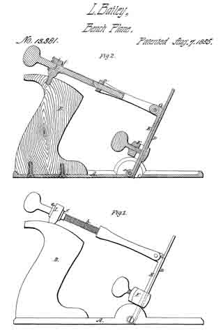
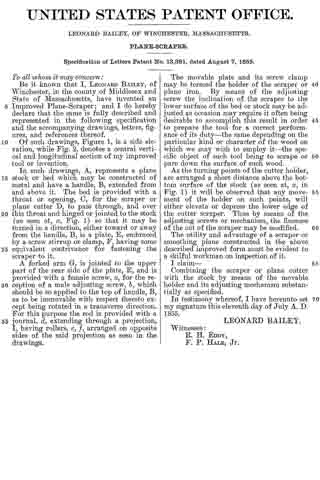
Of such drawings, Figure 1, is a side elevation, while Fig. 2, denotes a central vertical and longitudinal section of my improved tool or invention.
In such drawings, A, represents a plane stock or bed which may be constructed of metal and have a handle, B, extended from and above it. The bed is provided with a throat or opening, C, for the scraper or plane cutter D, to pass through, and over this throat and hinged or jointed to the stock (as seen at, x, Fig. 1) so that it may be turned in a direction, either toward or away from the handle, B, is a plate, E, embraced by a screw stirrup or clamp, F, having some equivalent contrivance for fastening the scraper to it.
A forked arm G, is jointed to the upper part of the rear side of the plate, E, and is provided with a female screw, a, for the reception of a male adjusting screw, b, which should be so applied to the top of handle, B, as to be immovable with respect thereto except being rotated in a transverse direction.
For this purpose the rod is provided with a journal, d, extending through a projection, I, having rollers, e, f, arranged on opposite sides of the said projection as seen in the drawings.
The movable plate and its screw clamp may be termed the holder of the scraper or plane iron. By means of the adjusting screw the inclination of the scraper to the lower surface of the bed or stock may be adjusted as occasion may require it often being desirable to accomplish this result in order to prepare the tool for a correct performance of its duty — the same depending on the particular kind or character of the wood on which we may wish to employ it — the specific object of such tool being to scrape or pare down the surface of such wood.
As the turning points of the cutter holder, are arranged a short distance above the bottom surface of the stock (as seen at, x, in Fig. 1) it will be observed that any movement of the holder on such points, will either elevate or depress the lower edge of the cutter scraper. Thus by means of the adjusting screws or mechanism, the fineness of the cut of the scraper may be modified.
The utility and advantage of a scraper or smoothing plane constructed in the above described improved form must be evident to a skilful workman on inspection of it.
I claim —
Combining the scraper or plane cutter with the stock by means of the movable holder and its adjusting mechanism substantially as specified.
In testimony whereof, I have hereunto set my signature this eleventh day of July A. D. 1855.
LEONARD BAILEY.
Witnesses:
R. H. EDDY,
F. P. HALE, Jr.