
No. 146,208 – Improvement In Plane-Guides (Walter S. Shipe) (1874)
| PLEASE NOTE: The images presented on this page are of low resolution and, as a result, will not print out very well. If you wish to have higher resolution files then you may purchase them for only $2.95 per patent by using the "Buy Now" button below. All purchases are via PayPal. These files have all been cleaned up and digitally enhanced and are therefore suitable for printing, publication or framing. Each zip package contains all the images below (some packages may contain more), and purchased files can be downloaded immediately. |
UNITED STATES PATENT OFFICE.
_________________
WALTER S. SHIPE, OF MINERVA, OHIO.
IMPROVEMENT IN PLANE-GUIDES.
_________________
Specification forming part of Letters Patent No. 146,208, dated December 18, 1874; application filed November 15, 1873.
_________________
To all whom it may concern:
Be it known that I, WALTER S. SHIPE, of Minerva, in the county of Stark and State of Ohio, have invented a new and Improved Plane-Guide, of which the following is a specification:
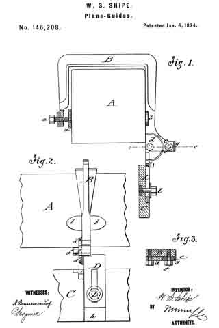
In the accompanying drawing, Figure 1 represents a sectional end view of my improved plane-guide as applied to a plane. Fig. 2 is a side view of the same 5 and Fig. 3, a detail horizontal section of the wide pivot on the line c c, Fig. 1.
Similar letters of reference indicate corresponding parts.
My invention relates to an improvement in plane-guides by which the plane is steadied in squaring or beveling to any desired angle without the use of a try-square or bevel; and consists of a yoke, which is firmly applied to the plane, and provided, at one end, with a pivoted guide-strip, which is adjusted by clamping-screws under any required angle to the plane.
In the drawing, A represents the plane; B, the yoke; and C, the guide-strip. The yoke B is rigidly applied to plane A by means of a clamp-screw, a, at one side, and a flanged extension, b, at the other side. The guide-strip C is applied to a connecting-piece, D, which is pivoted, by its semicircular part d, to the outwardly-projecting end of yoke B, below flanges b. The semicircular part d is beveled along its circumference, divided by degrees, and rigidly set to any angle to the plane by a curved wedge-piece, e, which is tightly secured between part d and the beveled projection g, at the outer end of yoke B, by a set-screw, f The slotted extension-piece D projects at a right angle to the semicircular part d, and slides in a recess, h, of guide-strip C, so that it may be carried up to the base of the plane, to be firmly secured by a fixed set-screw and washer, l.
When the plan is to be used with the guide for squaring, beveling, or jointing boards, veneers, &c., the yoke is placed over the plane, and firmly screwed thereon in such a manner that the center of the semicircular part d is slightly below the base of the plane. The set-screw at the edge of the are is then loosened, which allows the swinging of the guide-strip to any desired angle. If the angle between the guide-strip and base of the plane is oblique, the set-screw in the slotted part of piece D is loosened, to give greater play to the guide. When the guide is in position, the set-screw and wedge at the arc are tightened, and the guide moved up till it touches the base of the plane. The set-screw of the guide is then tightened on the slotted piece, and the plane ready for use, saving time and labor, and allowing of various applications in the trade.
Having thus described my invention, I claim as new and desire to secure by Letters Patent —
1. The plane-guide consisting of yoke B, with clamping- screw a, pivoted connecting-piece D, curved wedge-piece e, and guide-strip C, with fixed setscrew l, arranged and applied substantially as and for the purposes described.
2. The yoke B, having projecting end, forming the seat of the semicircular part d of piece D, and beveled projecting lug g, as set forth.
WALTER S. SHIPE.
Witnesses:
E. W. POORMAN,
GEO. W. PATTON.