| PLEASE NOTE: The images presented on this page are of low resolution and, as a result, will not print out very well. If you wish to have higher resolution files then you may purchase them for only $2.95 per patent by using the "Buy Now" button below. All purchases are via PayPal. These files have all been cleaned up and digitally enhanced and are therefore suitable for printing, publication or framing. Each zip package contains all the images below (some packages may contain more), and purchased files can be downloaded immediately. |
UNITED STATES PATENT OFFICE.
_________________
RICHARD BROWN, OF NEWARK, NEW JERSEY.
IMPROVEMENT IN GROOVING AND TONGUlNG PLANES.
_________________
Specification forming part of Letters Patent No. 149,026, dated March 31, 1874; application filed December 27, 1873.
_________________
To all whom it may concern:
Be it known that I, RICHARD BROWN, of the city of Newark, in the county of Essex and State of New Jersey, have invented certain Improvements in Grooving and Tonguing Planes, of which the following is a specification:
My invention relates to a match-plane adapted for cutting both tongues and grooves. The invention consists in the combination, with such plane, of a central guide, arranged between the two soles and stocks of the plane, and made capable of lateral adjustment in either direction, so as to adapt the plane to cut the tongue and groove in the edge of the lumber at a greater or less distance from the plane of one of the sides thereof, as may be required.
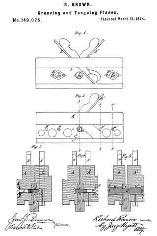
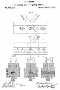
In the accompanying drawings, Figure 1 is a side elevation of my improved plane. Fig. 2 is an elevation thereof with one-half of the stock removed. Figs. 3, 4, and 5 are cross-sections, respectively, in lines x x, y y, and z z, Fig. 2.
Like letters of reference designate like parts in each of the figures.
A A’ represent the two stocks of the plane; B, the tonguing-iron, and B’ the grooving-iron, arranged in the stocks A A’, respectively, in the ordinary manner. C is the guide or fence, arranged centrally between the lower portions of the stocks A A’. It consists of a straight metallic bar or plate, of equal length with the stocks, having an upper and thinner portion, c, fitting in recesses formed in the adjacent sides of the two stocks, and a lower and wider portion, c’, projecting below the soles of the stocks, and resting against the same by means of rectangular shoulders or offsets, as clearly shown in Figs. 3 and 5.
The two stocks are connected with the guide C, so as to be capable of lateral adjustment, each independent of the other, in the following manner: D D represent two horizontal set-screws, arranged transversely in the stock A, near its ends, and working in threaded holes d in the portion c of the guide C. These set-screws are retained against lengthwise movement in the stock A by their heads turning in contact with the outer face of metallic washers E, secured in the side of the stock A, and a pin, f, passing through each set-screw in contact with the inner surface of said washers, or by equivalent means. D’ D’ represent two similar set-screws for connecting the stock A’ with the guide C. They are arranged in the same horizontal plane with the set-screws D D, but not so as to coincide therewith, as clearly shown in Fig. 2. G is a horizontal screw-bolt, arranged transversely and centrally in the guide C, as shown in Figs. 2 and 5, so that its ends project from either side of the guide into the two stocks A and A’, respectively, which latter are provided with suitable recesses for that purpose. The threaded bolt G is secured in the guide G by a pin or otherwise, to prevent it from turning in its seat. H H’ represent two tubular screws, or countersunk screw-nuts, engaging with the projecting ends of the screw-bolt G, and bearing, with their heads, against the sides of the stocks A and A’, respectively, which are, preferably, provided with countersunk metallic washers i as bearing-surfaces.
In Fig. 3 the two stocks A and A’ are shown in close contact with the central guide C, in which condition of the implement the groove and tongue are cut closer to the guide C, resting against the side of the board which is being operated upon.
In order to increase the distance at which the tongue or groove, or both, are cut from the guide C, the respective tubular screw is first sufficiently loosened, when the set-screws of the stock requiring adjustment are gradually turned, so as to screw out of the guide C, until the required distance is obtained, when the tubular screw is tightened, and the stock thereby firmly secured in this position.
The set-screws D D’ and bolt G are, preferably, arranged in the same horizontal plane, to prevent bending of the set-screws by the tightening of the nuts H H’.
Irons of different widths may be used in the implement, in order to adapt the same to lumber of different thicknesses.
The stocks are adjusted in the opposite direction, in an obvious manner, by the reversal of the above-described operation.
What I claim as my invention is —
The combination and arrangement, with the two stocks A A’, of the central adjustable guide C, set-screws D D’, bolt G, and screw-nut H H’, adapted to operate as and for the purposes set forth.
RICHARD BROWN.
Witnesses:
CHAS. E. HILL,
FREDERICK H. WOOLFALL.


