
| PLEASE NOTE: The images presented on this page are of low resolution and, as a result, will not print out very well. If you wish to have higher resolution files then you may purchase them for only $2.95 per patent by using the "Buy Now" button below. All purchases are via PayPal. These files have all been cleaned up and digitally enhanced and are therefore suitable for printing, publication or framing. Each zip package contains all the images below (some packages may contain more), and purchased files can be downloaded immediately. |
UNITED STATES PATENT OFFICE.
_________________
THOMAS D. WORRALL, OF BOSTON, MASSACHUSETTS.
METHOD OF SECURING PLANE-BITS.
_________________
Specification of Letters Patent No. 14,979, dated May 27, 1856.
_________________
To all whom it may concern:
Be it known that I, THOMAS D. WORRALL, of Boston, in the county of Suffolk, and State of Massachusetts, have invented an Improvemnt in Carpenters’ Molding-Planes; and I do hereby declare that the same is fully described and represented in the following specification and the accompanying drawings, of which —
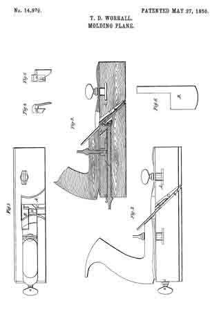
Figure 1, is a top view, and Fig. 2, a side elevation of a plane containing my improvement. Fig. 3, a vertical, central and longitudinal section of it. Fig. 4, a side view of the clamp to be hereinafter described. Fig. 5, a front view of said clamp. Fig. 6, a front view of the plane iron as removed from its stock.
The nature of my invention consists in an improved arrangement of clamping mechanism, or that used for retaining the plane-iron within the throat of its stock. In the said drawings A, denotes the stock; B, the cutter or plane-iron; and C, the throat of the stock.
In order to hold the plane iron within the stock, I employ a clamp or piece of metal, D, made to extend partially around it or embrace it and to be arranged with respect to it as seen in the drawings, the said clamp being placed in a recess a, leading out of the rear and upper part of the throat and made of a suitable size to allow the clamp to be moved backward far enough to draw the plane iron closely against the surface of the throat. A female screw, b, is formed through the rear part of the clamp and so as to receive a male screw, C’, out on the end of a long rod E, which extends longitudinally through the stock A and from its rear end to the clamp and has a shoulder, d, and a flat head or handle, e, as seen in the drawings. By turning the rod so as to cause the screw, C’, to enter the clamp, the said clamp may be drawn down closely upon the plane-iron so as to confine it closely or firmly in the throat of the stock.
By my arrangement of the confining contrivances, the throat of the plane-iron is not obstructed by any device, extending across it transversely, the plane cutter being held in place by the backward draft of the clamp and the bearing of the rod of the shoulder E, against the rear end of the plane stock.
I do not claim merely holding the plane or cutter in place in its throat by a wedge, screw, or equivalent device forced into the throat and across it and against the plane-iron, but
What I do claim is —
The arrangement of the clamp, D, and the screw rod E with respect to the plane cutter and its stock substantially as described.
In testimony whereof, I have hereunto set my signature this twenty-seventh day of February A. D. 1856.
THOS. D. WORRALL
Witnesses:
R. H. EDDY,
F. P. HALE, Jr.