
| PLEASE NOTE: The images presented on this page are of low resolution and, as a result, will not print out very well. If you wish to have higher resolution files then you may purchase them for only $2.95 per patent by using the "Buy Now" button below. All purchases are via PayPal. These files have all been cleaned up and digitally enhanced and are therefore suitable for printing, publication or framing. Each zip package contains all the images below (some packages may contain more), and purchased files can be downloaded immediately. |
UNITED STATES PATENT OFFICE.
_________________
CARL NORDELL, OF NEW YORK, N. Y.
IMPROVEMENT IN BENCH-PLANES.
_________________
Specification forming part of Letters Patent No. 158,302, dated December 29, 1874; application filed June 18, 1874.
_________________
To all whom it may concern:
Be it known that I, CARL NORDELL, of the city of New York, in the county and State of New York, have invented certain Improvements in Bench-Planes, of which the following is a specification:
The object of my invention is to furnish a hand-plane in which the tooth can be used shorter than in other planes, held in place and adjusted to the proper depth of cut and clearance for the shavings without the use of a double or covering tooth, or of the ordinary wedge, or the necessity of adjustment by hammering, and in which a durable metallic surface may be employed without liability of sticking to the surface of the work in consequence of the adhesion resulting from the well-known affinity between the metal and the rosin of the wood.
To accomplish this the invention consists, first, in a metallic cap, adjustable by means of a screw, or equivalent, to give the desired clearance for the shavings, and tightened against the tooth by means of a cam-lever pivoted to a screw adjusted in a threaded socket, which socket is pivoted on a spring-wire, or equivalent spring, which latter, held in permanent position at its two ends, allows ofa yielding at its middle to any extra or over pressure of the cam on the cap. This cap, with the cam-lever, thus does the purpose of the ordinary double or covering tooth and tightening-wedge. Second, in the combination of stationary springs with movable and adjustable screw-slides operating in the cap, and provided with cleats and stops, in such a manner that, when the cam-lever is thrown forward to loosen, but not remove, the cap, the tooth, which is provided with holes or slots suitable to encompass the said cleats, when the upper end of the tooth reaches the said stops, may be easily inserted between the said springs and the slides, and when pushed up against the said stops will be lodged on the said cleats by the pressure of the said springs, after which the depth of the tooth, or of the cut, is regulated. by operating the slides by means of its screws pivoted in the cap. When the cam is loosened the tooth may be instantly removed, when required, by simply pressing down the rear end of the cap against the ends of the springs placed under the tooth. This pressure raises the forward end of the cap sufficiently to release the tooth from the cleats, and allow it to slide out through the opening in the face of the plane. Third, in providing a combined metallic and wooden face of a plane by perforating or socketing the metallic face-plate, and inserting in the holes or sockets so formed one or more diffferent kinds of hard wood, placed with its grain or fibers at right angles to the face of the plane.
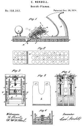
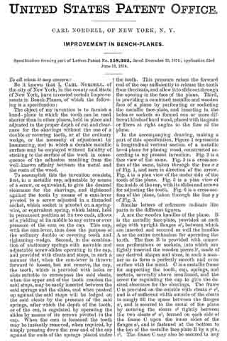
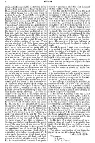
In the accompanying drawing, making a part of this specification, Figure 1 represents a longitudinal vertical section of a metallic hand-plane for planing wood, constructed according to my present invention. Fig. 2 is a face view of the same. Fig. 3 is a cross-section of the same, taken through the line x x of Fig. 1, and seen in direction of the arrow. Fig. 4 is a plan view of the under side of the tooth ofthe plane. Fig. 5 is a plan view of the inside of the cap, with its slides and screws for adjusting the tooth. Fig. 6 is a cross-section of the plane, taken through the line y y of Fig. 3.
Similar letters of reference indicate like parts in the different figures.
A are the wooden handles of the plane. B is the metallic face-plate, provided at each edge with upright flanges a1, between which are inserted and secured as well the handles A as the entire mechanism for operating the tooth. The face B is provided with numerous perforations or sockets, into which are tightly in serted the wooden pieces b’, made of any desired shapes and sizes, in such a manner as to form a perfectly smooth and even surface with the metal. C is a metallic frame for supporting the tooth, cap, springs, and sockets, severally above mentioned, and the screw for regulating the cap to give the desired clearance for the shavings. The frame C is provided on the outside with cleats c1 c2, and is of sufficient width outside of the cleats to snugly fill the space between the flanges a1, and is secured to the metal of the plane by entering the cleats c2 tightly between the two cleats a2 a3, formed on each side of the frame C upon the inner sides of the flanges a1, and is fastened at the bottom to the top of the metallic face-plate B by a pin, c3. The frame G may also be secured in any other suitable manner, the mode being immaterial so long as it be held firmly in its place. D are ribs or upright flanges of the frame C, upon which flanges the tooth rests when in position for work. A part of the lower portion of the frame C is formed into a socket, d1, placed across the face-plate of the plane, through which socket, and through holes in the lower part of the flanges D, is inserted a wire spring, d2, which spring also goes through and serves as pivot for the screw-socket E. This socket E is held in a central position in the frame C by being inserted through an oblong hole, e’, in the frame G, previous to the insertion, through the socket E, of the spring d2 The hole, being oblong, allows of an oscillating motion of the socket E, and thus also of a sliding motion of the cap. F are springs attached, with their lower ends, to the bottom of the frame C, and bearing, with their upper ends, against the under side of the tooth, to force the same, when being inserted, into its proper position against the cap, and retaining it there, even when the cap is partly released for adjustment of the cap or of the tooth. The upper cross-bar of the frame C is provided with a threaded hole for the reception of a thumb-screw, G, on which are formed a thumb-nut or milled wheel, g1, a shank, f1, and a button, g2. H is the cap, curved so as to touch with its forward end the lower or forward end of the tooth, whatever be the adjusted position of the cap. The rear end of the cap is formed into a downward-projecting flange, h1, in which is a slot, h2, fitting, when the cap is placed in position on the shank f1, between the thumb-nut g1 and button g2 of the screw G, the circumference of the thumb-nut g1 projecting far enough below the edge of the flange h1 to allow of turning the screw G, whereby the cap H is slid forward or withdrawn, according to the clearance desired for the shavings. In about the center of the cap H is a cup-shaped slotted socket for the reception of the spherical cam of the cam-lever I. This cam is slotted, and in its slot is pivoted the upper end of a screw, l’, the lower end of which enters the socket E. The cap H is also provided, at its upper or rear end, with slots h3, through which project, sufiiciently far to handle, the thumb-nuts j1 of the screws J. The forward ends of the screws J are pivoted in a rib, j2, forming a part of or attached to the cap H. The rear ends of the screws J are pivoted to the pieces i1, attached to the rear end of the cap H. On these pieces i1 are little projections i2, forming a cavity between them, for the reception of the rear ends of the springs F. K are slides, each threaded to form a nut, for the reception of one of the screws J, by turning which they are operated. Each slide K is provided with a cleat, k1, and a stop, k2. L is the tooth, the center of which is cut out so as to allow of its being slid back and forth without interfering with the screw I’ or socket E. In the rear ends of the tooth L are perforations l’, to receive, when the tooth is inserted, the cleats k1 of the slides K.
When the cam-lever is thrown in the position indicated by the dotted lines in Fig. 1, the springs F will raise the cap H sufliciently to allow (while slightly depressing the rear end of the cap H) of the introduction of the tooth L until it is checked by the stops k2 on the slides K. Allowing the springs F to expand, the tooth will be brought, with its slots l’, onto the cleats k1. By now turning either or both screws J, as the circumstances may require, by the hand-nuts j1, the tooth can be adjusted to the depth required, and its edge parallel to the face of the plane. The cap H is then adjusted by the screw G and hand-nut g1, to give the right clearance fbr the shavings. The cam-lever I is then tightened to depress the cap H, and the plane is ready for work.
Should the screw I’ have been turned down in its socket E too far for suiting a thicker tooth, the spring d2 will make up for the difference by yielding enough to allow of bringing the cam-lever down to the surface of the cap H in tightening the cam.
To remove the tooth it is only necessary to loosen the cam and depress slightly the rear end of the cap H.
Having thus described my invention, I claim as new and desire to secure by Letters Patent —
1. The cam and lever I, screw I’, and socket E, in combination with the spring d2, operating as described, and with the cap H, to hold the tooth firmly in place against the ribs D of
the frame C, substantially as specified.
2. The springs F, operating as described, in combination with the pieces i1 on the curved cap H, and the parts I I’ E, for the insertion and removal of the tooth L, and retaining the same while being adjusted, substantially as and for the purpose specified.
3. The screws J, working in the cap H, and provided with thumb-nuts j1, the slides K, with their cleats k1, and stops k2, in combination with the tooth L, provided with the slots l’, for the purpose of adjusting its position, substantially as and for the purpose specified.
4. The cap H, regulated by the screws G, the tooth L, regulated by the screws J and slides K, the cam and lever I, screw I’, socket E, and springs d2 F F, in combination with the frame C, face B, and handles A of a plane, to operate together in the manner and for the purposes substantially as specified.
5. The face of a plane, constructed by inserting pieces of wood b’ in a metallic face-plate, B, with the fibers at right angles to the face, substantially as and ibr the purpose specified.
The above specification of my invention signed by me this 15th day of June, 1874.
CARL NORDELL.
Witnesses:
D. PEARL,
H. W. E. PEARL.