| PLEASE NOTE: The images presented on this page are of low resolution and, as a result, will not print out very well. If you wish to have higher resolution files then you may purchase them for only $2.95 per patent by using the "Buy Now" button below. All purchases are via PayPal. These files have all been cleaned up and digitally enhanced and are therefore suitable for printing, publication or framing. Each zip package contains all the images below (some packages may contain more), and purchased files can be downloaded immediately. |
UNITED STATES PATENT OFFICE.
_________________
JUSTUS A. TRAUT, OF NEW BRITAIN, CONNECTICUT.
IMPROVEMENT IN BLOCK-PLANES.
_________________
Specification forming part of Letters Patent No. 159,865, dated February 16, 1875; application filed November 13, 1874.
_________________
To all whom it may concern:
Be it known that I, JUSTUS A. TRAUT, of New Britain, county of Hartford and State of Connecticut, have invented certain new and useful Improvement in Block-Planes, for carpenters or workers in wood; and to enable others skilled in the art to make the same I will proceed to describe it, referring to the drawing, in which the same letters indicate like parts.
The nature of this invention consists of an adjusting device, arranged at the back end of the stock, operated by a screw thumb-nut, to extend or withdraw the edge of the cutting-iron from the mouth or face of the plane; also, in firmly securing the cutting-iron, by means of a pad-lever and set-screw, arranged intermediate between the backend of said pad and the cutting-iron.
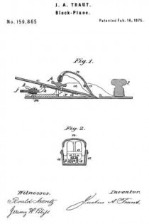
In the accompanying drawing, a is the plane-stock. d are inclined ribs, or cutting-iron supports, upon which the cutting-iron c is securely held and adjusted in the stock for use. b is an elongated perforated sliding plate, fitted closely, and slides freely in recess e, between and nearly flush with the upper edges of the incline ways or supports d. Said cutting-iron is provided with a fastening-pin, f which projects from the under side, and enters one of the orifices g. h is an extension or contracting bar, connected to the back end ofthe sliding plate b by a hinge-joint. It has a screw-thread, j, cut on its outer end, and is provided with a swivel screw-threaded thumb-nut, k, the swivel recess of which is secured in the stud m, so that by turning the thumb-nut k the cutting-iron c may be extended or withdrawn from the mouth of the plane, and be secured firmly in the desired position by a pad-lever, n, secured in the stock by, and oscillates on, a fulcrum-pin o, and compresses the front end of the cutting-iron c firmly to its bearing-surface by means of a thumb-screw, p, arranged in the back end, and intermediate between the lever-pad fn. and the face-surface of the cutting-iron c, entirely out of the way ot’ the operator’s hand. l is a finger-pad, for the forefinger to rest upon while in the hand in use.
It will be seen that great advantage is derived irom this improvement in adjusting or setting the iron to a proper cut, avoiding the usual annoyance of using a hammer or other tool in adjusting the cutting-iron, and in securing it in place.
It will be further seen that by arranging the set-screw p intermediate between the end of the pad n and the cutting-iron there will be no hinderance or obstruction to prevent the palm ofthe hand bearing easily and naturally upon the pad.
I am aware of the devices described in patents No. 144,828, of 1873, and 81,425, of 1868, and do not claim either; but
What I do claim is —
In a plane, substantially as herein described, the cutting-iron having a fixed fastening-pin, and the perforated sliding plate, with the thumb-screw and bar, by which the iron may be adjusted, and the thumb-screw and pad, by which it may be fastened in position, all combined and constructed to operate as set forth.
JUSTUS A. TRAUT. [L. S.]
Witnesses:
ROALD ARENTZ,
JEREMY W. BLISS.


