
| PLEASE NOTE: The images presented on this page are of low resolution and, as a result, will not print out very well. If you wish to have higher resolution files then you may purchase them for only $2.95 per patent by using the "Buy Now" button below. All purchases are via PayPal. These files have all been cleaned up and digitally enhanced and are therefore suitable for printing, publication or framing. Each zip package contains all the images below (some packages may contain more), and purchased files can be downloaded immediately. |
UNITED STATES PATENT OFFICE.
_________________
ASAHEL H. DEAN, OF PHILADELPHIA, PENNSYLVANIA.
IMPROVEMENT IN BENCH-PLANES.
_________________
Specification forming part of Letters Patent No. 161,213, dated March 23, 1875; application filed January 30, 1875.
_________________
To all whom it may concern:
Be it known that I, ASAHEL H. DEAN, of Philadelphia, Pennsylvania, have invented certain Improvements in Bench-Planes, of which the following is a specification:
The main object of my invention is to so construct a plane having a metal body or frame as to admit of the ready withdrawal, replacing, and adjustment of the plane-bit, and this object I attain in the manner which I will now proceed to describe, reference being had to the accompanying drawings, in which —
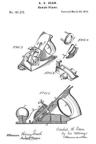
Figure 1 is a vertical section of my improved plane; Fig. 2, perspective view of the lever-clamp; Fig. 3, a perspective view of the plane; and Fig. 4, views illustrating part of my invention.
The body of the plane consists of the base A and two side pieces or cheeks, B and B’, the whole being, in the present instance, cast in one piece. The handle E of the plane and the knob F are secured to the base A by screws, in the manner shown in Fig. 1. The plane iron or bit C, which is of the usual construction, and has the usual cap plate h’, bears against a projection, j, of the wooden handle and against a shoulder, i, on the base, the cutting-edge of the bit projecting through a slot in the said base in the ordinary manner, and the bit being confined to its place by a lever-clamp, H, best observed in the perspective views, Figs. 2, 3, and 4. This clamp has on one side a segmental projection adapted to a circular opening in the cheek B, and on the opposite side a ring, f, adapted to a segmental groove, h, formed in the outer face of the cheek B. The projection e and ring f constitute the pivots or fulcrums of the lever-clamp, the upper end of which is caused to bear on the cap-plate by a set-screw, d, in a manner too clearly indicated by the drawing to need description, and to confine the bit to the shoulder on the base and the projection j of the handle.
After loosening the set~screw d, and thereby releasing from its bearings the lever-clamp H, the latter can be removed laterally, its projection e from the cheek B and its ring f from the segmental recess of the cheek B’, thereby permitting the plane-bit to be withdrawn, the clamp being as readily introduced into its place and secured after the adjustment of the plane-bit.
The bearing of the bit on the wooden handle E is an important feature of my invention, for the wood presents a surface to which the bit can be more firmly secured without danger of slipping, when the plane is subjected to accidental jars, than a metal surface.
I claim as my invention —
I. A plane in which the bit is confined to its bearings by a lever-clamp, H, constructed for connection to, and lateral withdrawal from, the frame or body of the plane, substantially in the manner described.
2. The clamp H, its set-screw d, projection e, and ring f, in combination with the cheek B, having an opening adapted to the said projection, and the cheek B, having a segmental recess adapted to the said ring, all substantially as set forth.
3. A plane having a metal body or frame, a wooden handle, and a retaining-screw, or its equivalent, between which and the handle the plane-bit is clamped, all substantially as described.
In testimony whereof I have signed my name to this specification in the presence of two subscribing witnesses.
ASAHEL H. DEAN.
Witnesses:
HUBERT HOWSON,
HARRY SMITH.