
| PLEASE NOTE: The images presented on this page are of low resolution and, as a result, will not print out very well. If you wish to have higher resolution files then you may purchase them for only $2.95 per patent by using the "Buy Now" button below. All purchases are via PayPal. These files have all been cleaned up and digitally enhanced and are therefore suitable for printing, publication or framing. Each zip package contains all the images below (some packages may contain more), and purchased files can be downloaded immediately. |
UNITED STATES PATENT OFFICE.
_________________
WILLIAM JOHNSTONE, OF MONTREAL, CANADA, ASSIGNOR OF ONE-HALF HIS RIGHT TO WILLIAM WHITEHEAD ROBERTSON, OF SAME PLACE.
IMPROVEMENT IN BENCH-PLANES.
_________________
Specification forming part of Letters Patent No. 161,516, dated March 30, 1875; application filed March 1, 1875.
_________________
To all whom it may concern:
Be it known that I, WILLIAM JOHNSTONE, of the city and district of Montreal, in the Province of Quebec, in the Dominion of Canada, pattern-maker, have invented an Improvement on Bench-Planes, of which the following is a specification:
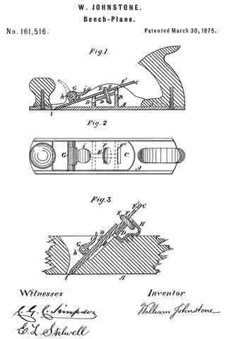
My invention relates to the adjustment of the plane-iron by means of a nut working on a screw, so that by simply turning the nut the plane-iron is drawn into or pushed out irom the body of the plane, and when at the desired place is held there firmly by a catch in the shape of an eccentric or cam, reference being had to the annexed drawings, where similar letters indicate like parts, and where —
Figure 1 represents a sectional elevation of an iron plane embodying my invention. Fig. 2 represents a plan of Fig. 1. Fig. 3 represents a modification adapting it to wooden planes.
Letter A is the body of the plane, having two cross-bars or partitions, B B, formed in it, extending up to the under side of the plane-iron C, and of such height that the plane-iron is supported at the proper angle. In the bars B B, and extending from one to the other, is fixed, by any suitable means, a screw, D, on which is a flat nut, E, having its edge milled to adord a better hold and prevent the fingers or thumb of the person using it from slipping. This nut E passes through the slit F in the plane-iron C, and projects a short distance beyond it. The plane-iron C is held fast by the cam G. This cam is turned on the pin h by means of the handle i, and when in the position shown in the drawings by firm lines the projecting part k presses tight on the plane-iron C, and holds it firmly against the bars B B and the beveled edge of the hole l.
When it is desired to adjust the plane-iron the cam G is thrown up into the position shown by the dotted lines in Fig. 1. The plane-iron C is now free to be moved, which is done by placing the thumb or finger on the projecting part of the nut E and turning it round. This causes it to move up or down the screw D, and its side being in contact with the side of the slit F in the plane-iron C compels it to move in the same direction with it. When in the required position the cam G is turned down and holds it there.
The plane-iron C is provided with one or more additional slits, F’, to be used when it becomes shorter by the wearing away of its cutting-edge.
The modification shown in Fig. 3 consists of the piece H, of any suitable configuration, firmly secured to the wooden body of the plane in place of the bars B B to carry the screw D;
the remainder of the parts being the same as above described in connection with planes having bodies of iron, with the exception that a passage is cut through the projecting part k of the cam G, to allow the nut n. to pass when the plane-iron C is worn short.
By these arrangements I am enabled to adjust the plane-iron with greater nicety, and more easily and expeditiously than by the old method.
What I claim as my invention is —
The plane A, having bars B B, in combination with screw D, nut E, and plane-iron C, having slits F and F’, substantially as and for the purposes described.
WILLIAM JOHNSTONE.
Witnesses:
C. G. C. SIMPSON,
E. L. STILWELL.