
| PLEASE NOTE: The images presented on this page are of low resolution and, as a result, will not print out very well. If you wish to have higher resolution files then you may purchase them for only $2.95 per patent by using the "Buy Now" button below. All purchases are via PayPal. These files have all been cleaned up and digitally enhanced and are therefore suitable for printing, publication or framing. Each zip package contains all the images below (some packages may contain more), and purchased files can be downloaded immediately. |
UNITED STATES PATENT OFFICE.
_________________
ELLIOT G. STORKE, OF AUBURN, NEW YORK.
IMPROVEMENT IN CARPENTERS’ PLANES.
_________________
Specification forming part of Letters Patent No. 162,710, dated April 27, 1875; application filed January 6, 1875.
_________________
To all whom it may concern:
Be it known that I, ELLIOT G. STORKE, of Auburn, New York, have invented certain new and useful Improvements in Carpenters’ Planes, of which the following is a specification:
My improvements relate to setting and fastening the bits of planes, and also to means for giving to bench-planes a metallic and adjustable throat-piece.
The nature of my invention can best be explained by reference to the accompanying drawings, in which —
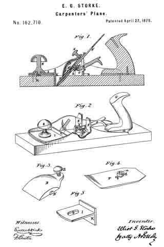
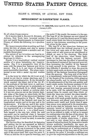
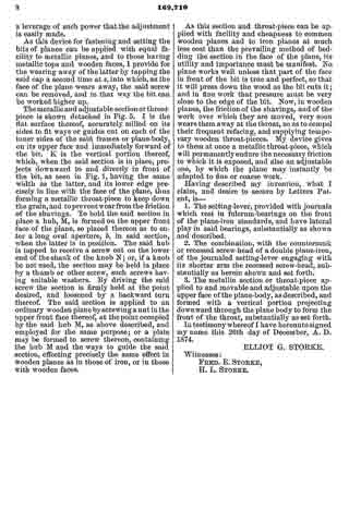
Figure 1 is a longitudinal vertical central section of a plane embodying my improvements. Fig. 2 is a perspective view of the same with the plane-iron fastener and bit removed. Fig. 3, 4, 5, are views of detached parts hereinafter described. The plane represented is one with a metal top and wooden face.
A is the lever by which the bit is set or adjusted to cut fine or coarse shavings, and Y its upward-projecting point; B, the standards which support the upper end of the bit B’; C, the journals of the said lever A, said journals resting in bearings cut in projections on the front of standards B, in which bearings the journals have a lateral or end-wise play. L L are two grooves cut on the interior opposite sides of the frame or plane-body, for the reception of lugs D’ of the plane-iron fastener D, shown in perspective in Fig. 3. The lugs are on the sides of the fastener and near its longitudinal center, and at its rear end is the thumb-screw. F is the cap and G the screw of an ordinary plane-iron, the screw-head being countersunk at at to receive the globular point Y of the lever A. s is a blank screw-hole tapped in the cap, into which the said cap-screw can be removed when it becomes necessary, by the wearing away of the wooden face of the plane, if such be used, to raise the cutting-iron.
The devices thus far described for fastening and setting the bit are operated as follows: The lever A is placed in its bearings in the standards B; the cap is screwed in the usual way upon an ordinary plane-iron, and the recess in the screw-head laid upon the point Y. When so laid the bit is upon its bearings, and the point Y fits neatly the recess a in the cap. The lugs D’ of the fastener are now placed in the grooves L L and the thumb-screw E tightened, which binds the bits to its bearings with more or less firmness, according to the pressure given by the screw.
The lugs D’ of the plane-iron fastener are introduced into the inclined grooves L L at the lower and open ends of the latter. The upper ends of said grooves are shouldered or closed, as seen in the drawing. The thick heel of the plane-iron, when drawn back, tends to force the fastener upward. This movement in time has the effect of smoothing the surfaces of contact of the lugs and grooves, thus increasing the liability of the fastener to work upward in the grooves. To remedy this difficulty l shoulder or close the grooves at their upper ends, as shown, thus preventing liability of the fastener becoming disengaged from the grooves. The long arm of the lever A is immediately under and within easy reach of the fingers of the workman, while grasping the plane-handle, and by raising or lowering it the adjustments of the bits are quickly and easily made, under the firmest pressure of the screw. I so construct the lever with a central hub bearing accurately-turned journals at its ends, with the spherical point Y rising upward from its center, and from which extends the long arm toward the plane-handle, that all its parts, being in one piece, are wrought with much greater facility, accuracy, and economy, and placed and maintained in position more easily and firmly than if separate pieces were employed in its construction, and so also that its journals have a free and accurate lateral or sidewise movement, by which the upper end of the bit, when fastened, can be so pushed to right or left as to square its cutting-edge with the face of the plane. By connecting the spherical point Y with the screw-heads of double plane-irons, I obtain not only a very cheap, but a very efficient means of adjusting them, for these screw-heads always maintain, practically, the same position, relatively to the cutting-edge of the bit, and can be countersunk at a merely nominal cost. The sweep of the long arm of the lever A carries the point Y through a sufficient arc to give the required adjustment to the bit, and a leverage of such power that the adjustment is easily made.
As this device for fastening and setting the bits of planes can be applied with equal facility to metallic planes, and to those having metallic tops and wooden faces, I provide for the wearing away of the latter by tapping the said cap a second time at s, into which, as the face of the plane wears away, the said screw can be removed, and in that way the bit can be worked higher up.
The metallic and adjustable section or throat-piece is shown detached in Fig. 5. I is the flat surface thereof, accurately milled on its sides to fit ways or guides out on each of the inner sides of the said frames or plane-body, on its upper face and immediately forward of the bit. K is the vertical portion thereof, which, when the said section is in place, projects downward to and directly in front of the bit, as seen in Fig. 1, having the same width as the latter, and its lower edge precisely in line with the face of the plane, thus forming a metallic throat-piece to keep down the grain, and to prevent wear from the friction of the shavings. To hold the said section in place a hub, M, is formed on the upper front face of the plane, so placed thereon as to enter along oval aperture, b, in said section, when the latter is in position. The said hub is tapped to receive a screw cut on the lower end of the shank of the knob N; or, if a knob be not used, the section may be held in place by a thumb or other screw, such screws having suitable washers. By driving the said screw the section is firmly held at the point desired, and loosened by a backward turn thereof. The said section is applied to an ordinary wooden plane by screwing a nut in the upper front face thereof, at the point occupied by the said hub M, as above described, and employed for the same purpose; or a plate may be formed to screw thereon, containing the hub M and the ways to guide the said section, effecting precisely the same edect in wooden planes as in those of iron, or in those with wooden faces.
As this section and throat-piece can be applied with facility and cheapness to common wooden planes and to iron planes at much less cost than the prevailing method of bedding the section in the face of the plane, its utility and importance must be manifest. No plane works well unless that part of the face in front of the bit is true and perfect, so that it will press down the wood as the bit cuts it; and in line work that pressure must be very close to the edge of the bit. Now, in wooden planes, the friction of the shavings, and of the work over which they are moved, very soon wears them away at the throat, so as to compel their frequent refacing, and supplying temporary wooden throat-pieces. My device gives to them at once a metallic throat-piece, which will permanently endure the necessary friction to which it is exposed, and also an adjustable one, by which the plane may instantly be adapted to fine or coarse work.
Having described my invention, what I claim, and desire to secure by Letters Patent, is —
1. The setting-lever, provided with journals which rest in fulcrum-bearings on the front of the plane-iron standards, and have lateral play in said bearings, substantially as shown and described.
2. The combination, with the conntersunk or recessed screw-head of a double plane-iron, of the journaled setting-lever engaging with its shorter arm the recessed screw-head, substantially as herein shown and set forth.
3. The metallic section or throatpiece applied to and movable and adjustable upon the upper face ofthe plane-body, as described, and formed with a vertical portion projecting downward through the plane body to form the front of the throat, substantially as set forth.
In testimony whereof I have hereunto signed my name this 26th day of December, A. D. 1874.
ELLIOT G. STORKE.
Witnesses:
FRED. E. STORKE,
H. L. STORKE.