
| PLEASE NOTE: The images presented on this page are of low resolution and, as a result, will not print out very well. If you wish to have higher resolution files then you may purchase them for only $2.95 per patent by using the "Buy Now" button below. All purchases are via PayPal. These files have all been cleaned up and digitally enhanced and are therefore suitable for printing, publication or framing. Each zip package contains all the images below (some packages may contain more), and purchased files can be downloaded immediately. |
UNITED STATES PATENT OFFICE.
_________________
HARRISON P. TAYLOR, OF MINERVA, OHIO, ASSIGNOR TO HIMSELF AND P.
A. PAINTER, OF SAME PLACE.
IMPROVEMENT IN GUIDES FOR BENCH-PLANES.
_________________
Specification forming part of Letters Patent No. 165,132, dated June 29, 1875; application filed May 28, 1875.
_________________
To all whom it may concern:
Be it known that I, HARRISON P. TAYLOR, of Minerva, in the county of Stark and State of Ohio, have invented an Improvement in Guides for Bench-Planes, of which the following is a specification:
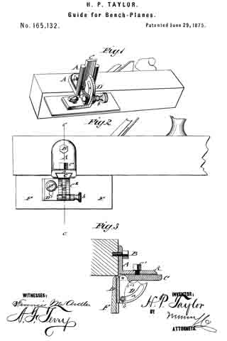
Figure 1 represents a perspective view of my improved plane-guide, as attached to a plane. Fig. 2 is an end view, and Fig. 3 a vertical section, of the same on the line c c, Fig. 2.
Similar letters of reference indicate corresponding parts.
The object of my invention is to provide an improved double adjustable plane-guide that may be readily set to any angle, and to any part on the face of the plane, that the whole width of the bit is used and the true face of the plane preserved.
The invention consists of a rectangular slotted or dovetailed piece that is attached to the side of the plane, and provided with a sliding piece, with guide-arms tor the pivoted, graduated, and slotted piece, which is set by a clamp screw, and attached by a slotted base-plate to the beveled guide-strip.
In the drawing, A represents the rectangular piece, by which the guide is attached to the side of the plane by a set-screw, B, passing through a slot or perforation of the same. The free end of piece A is either provided with a dovetail groove at the under side, or with a plain slot tor the purpose of guiding the sliding rectangular piece C, having dovetail or tongue, into any position, to any point on the face of the plane, or in opposite direction to some distance from the same, as required. The sliding piece C is firmly secured when adjusted by a set-screw, C1. The downward-extending part of slide-piece C forms, by a dividing recess, two guide-arms or standards, C2, between which the quadrantal piece D is pivoted, and by means of slot a and set-screw b set to any angle toward the face ofthe plane, according to the graduation of its circumference. A base-plate, D’, at right angles to the quadrantal part, carries, by slot and clamp-screw, a beveled wooden or iron guide-strip, F, which may be brought up to the edge and face of the plane. One or two guides may be used, according to the length of plane or material. The guide attachment is removed by detaching the fastening-screw of the rectangular piece A from the side of the plane, or by leaving the same on the plane, using it as a handle, and taking off the slide-piece with the rest of the attachment.
The guide may be adjusted to use the plane square or at any bevel, the main advantage being the sliding of the guide-strip under the face of the plane.
Having thus described my invention, I claim as new and desire to secure by Letters Patent —
The combination of plate A, slide C, single set-screw C1, and quadrant D, all constructed and arranged as and for the purpose specified.
HARRISON P. TAYLOR.
Witnesses:
JOHN BREIDENSTEIN,
HERBERT NICKELSON.