
| PLEASE NOTE: The images presented on this page are of low resolution and, as a result, will not print out very well. If you wish to have higher resolution files then you may purchase them for only $2.95 per patent by using the "Buy Now" button below. All purchases are via PayPal. These files have all been cleaned up and digitally enhanced and are therefore suitable for printing, publication or framing. Each zip package contains all the images below (some packages may contain more), and purchased files can be downloaded immediately. |
UNITED STATES PATENT OFFICE.
_________________
JOSEPH LOOK, OF SOUTH ABINGTON, MASSACHUSETTS, ASSIGNOR TO BRIGHAM, LITOHFIELD & VINING, OF SAME PLACE.
IMPROVEMENT IN JOINERS’ PLANES.
_________________
Specification forming part of Letters Patent No. 165,742, dated July 20, 1875; application filed March 15, 1875.
_________________
To all whom it may concern:
Be it known that I, JOSEPH LOOK, of South Abington, of the county of Plymouth and State of Massachusetts, have invented a new and useful Improvement in Joiners’ Planes; and do hereby declare the same to be fully described in the following speciiication and represented in the accompanying drawings, of which —
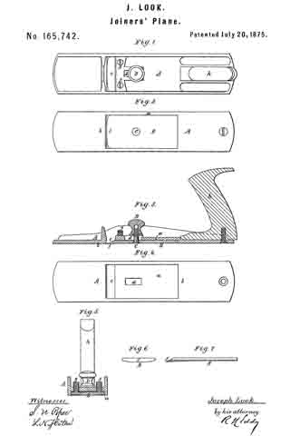
Figure 1 is a top view, Fig. 2 a bottom view, and Fig. 3 a longitudinal section, of one of my improved planes. Fig. 4 is a bottom view, and Fig. 5 a transverse section, of the stock. Fig. 6 is a front-end view, and Fig. 7 an edge view, of the cutter or plane-iron, which is crowned or curved transversely on its lower surface for some distance back from the cutting-edge.
The plane is designed for cutting or planing across the grain of wood perpendicularly, or about so, thereto. Instead of arranging the cutting-iron sloping in the stock, or at an acute angle to the bearing-surface of the plane, it is disposed substantially or approximately parallel thereto, and is wholly arranged within the stock, or a cavity or recess made lengthwise therein, the cutter being on its under surface, and at and back from its cutting edge, arched or crowned a little transversely, as shown.
In the drawing, A denotes the stock, made with a cutter-receiving recess, a, arranged in it, and with respect to its bearing-face b, in manner as shown, there being a chip-throat, c, leading upward out of said recess a and through the stock, in manner as represented. Besides the said throat c, there is a slot, d, arranged lengthwise in the stock, and to open upward out of the recess a. The cutter or plane-iron shown at B is placed flatwise in the recess a, and with the rear part of its lower surface flush with the bearing-surface b, the cutting-edge f projecting partly across the chip-throat. A screw, C, formed as shown, goes up through a countersunk hole in the cutter, and also through the slot d, and is provided with a clamp-nut, D, such serving to hold the cutter in place in the stock. In advance of the said screw and nut are two adjusting-screws, g g, which, arranged as shown, screw down into and through the stock and against the plane-iron, they serving to determine the projection of its cutting-edge below the bearing surface of the stock, such stock being provided with a handle, h, arranged as represented.
It will be seen, that while such a plane is being used to cut across the end or grain of a piece of wood, the cutter will stand at, or nearly at, a right angle with the said grain. and therefore will operate to much better advantage than a cutter having a slanting position in the stock, as plane-irons are usually arranged.
I prefer to curve or crown the cutter in manner as shown and described, but a plane-
surface cutter may be used. The curved one, however, for various kinds of planing, especially for reduction of vessels knees or ribs, will operate much better than a plane-surface cutter.
I claim —
In the improved plane, the cutter B, its receiving-recess a, chip-throat c, and holding and adjusting screws C D, g g, arranged in and with the slotted bottom of the stock A, all substantially as described and shown.
JOSEPH LOOK.
Witnesses:
GEORGE A. CLIFT,
ALBERT DAVIS.