| PLEASE NOTE: The images presented on this page are of low resolution and, as a result, will not print out very well. If you wish to have higher resolution files then you may purchase them for only $2.95 per patent by using the "Buy Now" button below. All purchases are via PayPal. These files have all been cleaned up and digitally enhanced and are therefore suitable for printing, publication or framing. Each zip package contains all the images below (some packages may contain more), and purchased files can be downloaded immediately. |
UNITED STATES PATENT OFFICE.
_________________
DAVID F. WILLIAMS, OF WOONSOCKET, RHODE ISLAND, ASSIGNOR TO BAILEY TOOL COMPANY, OF SAME PLACE.
IMPROVEMENT IN BENCH-PLANES.
_________________
Specification forming part of Letters Patent No. 166,239, dated August 3, 1875; application filed May 24, 1875.
_________________
To all whom it may concern:
Be it known that I, DAVID F. WILLIAMS, of Woonsocket, Providence Plantations, and in the State of Rhode Island, have invented a new and useful Improvement in Bench-Planes; and I do hereby declare that the following is a full, clear, and exact description thereof, reference being had to the accompanying drawings making a part of this specification.
This invention relates to a bench-plane having a flexible steel face to allow of its being adjusted to operate upon any given circle or arc of a circle in either a concave or convex form; and it consists in certain improvements in the mode of fixing or holding the face after it has been bent to the desired curve, substantially as hereinafter more fully set forth, the object being to simplify the construction of the plane, and at the same time to secure a firmer adjustinent of the flexible face.
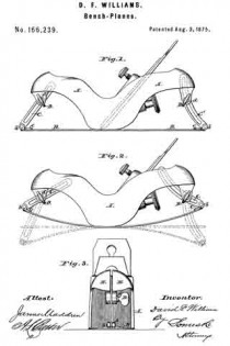
Figure 1 in the drawing shows the plane adjusted to operate upon a plane surface. Fig. 2 shows it adjusted to operate upon a concave surface, the dotted lines also indicating the position of the movable parts when the face is adjusted to operate upon a plane and on a convex surface. Fig. 3 is a front view, showing the opening in the stock and the slotted arm attached to the face-plate, which slides therein.
A in the drawings represents a metallic plane-stock, cast in the usual form for this class of planes. B is the flexible face of steel, made thinnest at its ends, and tapering from the center of its length, in order that when bent it may form a perfect curve. It is attached to the stock by means of screws on each side of the month of the plane. The ends of the plane-stock are split, as shown at a, Fig. 3, forming jaws E E, and, provided with set-screws D D, form clamps for the slotted arms C C’, which are attached, respectively, to the ends of the flexible shoe B. These screws pass through one side of the divided end of the plane-stock, and through the slot in said arms, and are screwed into threads formed in the other side or jaw of the clamp or stock, and, being provided with shoulders d, operate to tightly clamp the jaws. The arms C C’ are attached to the flexible shoe by being hinged at b to a piece, c, which is riveted to the shoe.
As the screws D are loosened, and the shoe B is bent in either direction the arms C C’ slide on the screws D in their slots, and permit the adjustment of the shoe to any desired curve.
The arm C’ is bent to prevent contact with the upper part of the plane-iron when the shoe is bent to a convex form.
What is claimed as the invention is —
1. A bench plane having a flexible face, in which the stock is split at either end to form a clamp, substantially as described.
2. The combination of the flexible shoe B, slotted arms C C’ hinged thereto, clamping-jaws E, and set-screws D, substantially as described.
D. F. WILLIAMS.
Witnesses:
WM. H. BAILEY,
J. E. BLOOD.


