| PLEASE NOTE: The images presented on this page are of low resolution and, as a result, will not print out very well. If you wish to have higher resolution files then you may purchase them for only $2.95 per patent by using the "Buy Now" button below. All purchases are via PayPal. These files have all been cleaned up and digitally enhanced and are therefore suitable for printing, publication or framing. Each zip package contains all the images below (some packages may contain more), and purchased files can be downloaded immediately. |
UNITED STATES PATENT OFFICE.
_________________
DAVID F. WILLIAMS, OF WOONSOOKET, RHODE ISLAND, ASSIGNOR TO BAILEY TOOL COMPANY, OF SAME PLACE.
IMPROVEMENT IN BENCH-PLANES.
_________________
Specification forming part of Letters Patent No. 166,240, dated August 3, 1875; application filed May 24, 1875.
_________________
To all whom it may concern:
Be it known that I, DAVID F. WILLIAMS, of Woonsocket, Providence Plantations, and in the State of Rhode Island, have invented a new and useful Improvement in Bench-Planes; and I do hereby declare that the following is a full, clear, and exact description thereof, reference being had to the annexed drawings making part of this specification, in which —
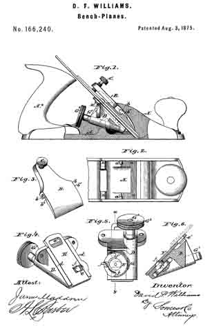
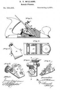
Figure 1 is a side elevation of my improved bench-plane, one of the cheeks of the stock being broken away to show more clearly the means for clamping and adjusting the bit. Fig. 2 is a plan view of the forward end of the stock. Fig. 3 is a perspective view of the clamping-plate and screw. Fig. 4 is a perspective view of the bit-adjusting mechanism. Fig. 5 is a view ofthe under side ofthe same. Fig. 6 is a section thereof, taken in planes indicated by the broken line x y in Fig. 5.
The same letters of reference are used in all the figures in the designation of identical parts.
The nature of my invention consists, first, in the employment of a clamping-plate and screw for fixing the bit after proper adjustment, the clamping-plate having open bearings at about its mid-length in its side edges, for the reception of fixed studs projecting inwardly from the cheekplates of the stock; secondly, in the use ofa sliding plate so combined with mechanism for sliding it in its seat, and the head of the screw used for securing the cap to the bit, as to afford a convenient means for accurately adjusting the bit with the right hand, while holding on to the tail-handle of the plane with the left.
The stock A, made of metal, in substantially the form shown, is provided with the usual throat, through which the bit projects, and also with inclined surfaces a, for supporting the bit in part. The bit is secured by a lever or clamping-plate, B, pivoted above it to the cheek-plates of the stock, and provided at its upper end with a set-screw, C, to press against the cap of the bit, thereby causing the lower end of the clamping-plate to also forcibly bear on the cap of the bit. It is pivoted upon short fixed studs a’, projecting inwardly from the cheek-plates of the stock, and is provided with open bearings b, formed in its side edges, in such a way that it may be slid upon said studs, which enter their bearings through chambers b’, formed in the under side of the clamping-plate. Supports for the plane-iron, having inclined surfaces a, against which said iron rests, are cast upon the inner side of each of the flanges of the stock A. Between these supports for the plane-iron, underneath the latter, is inserted a frame, D, which contains the mechanism by means of which the plane is adjusted, said frame being screwed to the supports referred to through ears cast thereon. The flanges of this frame D lie in the same plane as the supporting surfaces a, and assist in forming a bed for the plane-iron. Between the flanges is a plate, E, which slides in dovetailed grooves formed in said flanges. This plate has a notch, e, which receives a crank-pin, f This crank-pin projects eccentrically from the hub of a sectional worm-wheel, F, arranged in a recess in the under side of frame D. Wheel F meshes into a worm, G, on a shaft, GI, which turns in a bearing of frame D, and is provided at its outer rear end with a milled head or button, G2, which secures the cap to the bit.
The plate E moves in a plane parallel to the bit-supporting surfaces, so that by sliding it by means of the crank and worm-gearing described, the bit may be accurately and readily adjusted.
The non-toothed portion of the worm-wheel F is of smaller radius than the toothed portion, forming shoulders f1 at the junction, which bring up against a stop-pin, f2, whenever the worm-wheel has been turned in either direction to the extent of the throw of the crank-pin f.
The milled head or button G2 is in convenient proximity to the tail-handle A2 of the stock, for operating it with the thumb and fingers of the right hand, while holding on to the tail-handle.
In addition to its described function of moving the plate E., the worm-gearing constitutes a lock, holding the plate, and consequently the bit connected to it, by means of the head of screw H, firmly in position against sliding, thus assisting the clamping-plate in this office.
I do not claim a cap or presser plate made to slide in grooves formed in the sides of the stock, as shown and described in the patent, now expired, granted W. S. Loughborough, April 4, 1854.
What is claimed as the invention is —
1. In a bench-plane, a clamping-plate having open bearings in its side edges, with channels leading thereto in its under side. substantially as and for the purpose set forth.
2. The combination of the stock A, with studs a’, the bit and its cap, and the clamp-
ing-plate B, with channeled openings b b’, substantially as described.
3. In a bench-plane, the combination of the sliding plate, crank-pin, worm, and worm-wheel, substantially as described.
4. The combination of the plane-iron and its cap, the uniting-screw, and the slotted sliding plate with means for operating the same, substantially as described.
5. The sectoral worm-wheel F, having shoulders at f1 f1, in combination with the stop-pin f2 and the worm G G1, substantially as described.
D. F. WILLIAMS.
Witnesses:
WM. H. BAILEY,
J. E. BLOOD.


