
| PLEASE NOTE: The images presented on this page are of low resolution and, as a result, will not print out very well. If you wish to have higher resolution files then you may purchase them for only $2.95 per patent by using the "Buy Now" button below. All purchases are via PayPal. These files have all been cleaned up and digitally enhanced and are therefore suitable for printing, publication or framing. Each zip package contains all the images below (some packages may contain more), and purchased files can be downloaded immediately. |
UNITED STATES PATENT OFFICE.
_________________
JOSEF NICHT, OF AUBURN, NEW YORK.
IMPROVEMENT IN BENCH-PLANES.
_________________
Specification forming part of Letters Patent No. 173,177, dated February 8, 1876; application filed July 29, 1875.
_________________
To all whom it may concern:
Be it known that I, JOSEF NICHT, of Auburn, in the county of Cayuga and State of New York, have invented certain new and useful Improvements in Bench-Planes; and that the following is a full, clear, and exact description of the same, reference being had to the accompanying drawings making a part of this specification, in which —
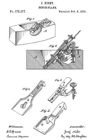
Figure 1 represents a perspective view of my improved plane, with the plane-irons and fastening-cap removed. Fig. 2 represents a longitudinal vertical section through my improved plane. Fig. 3 represents a detached view of the mechanism employed for raising or lowering the plane-irons. Fig. 4 represents a perspective view ofthe cap overlying the plane-irons, showing its under side and connected wedge. Fig. 5 represents a modification of the same.
Similar letters of reference, where they occur, denote like parts in all the figures.
My invention relates to certain combinations of mechanisms used to set or adjust plane-irons from the exterior of the plane without separating the parts, and with great expedition and accuracy.
My invention relates also to the means by which the plane-irons can be moved laterally to adjust them in that direction, and also to the means by which the plane-irons are retained in position by means of a cap and wedge.
To enable others skilled in the art to make and use my invention, I will proceed to describe the same with reference to the drawings.
A represents the wooden stock of a plane, to which is attached, by means of the screw a, the plate B, that has formed on its under side bearings b for the shaft c, around which the geared segment and lever C revolve. The rear end of this lever C is slotted, so as to fit over a pin formed on one side of the nut d, that is raised or lowered by a screw-shaft, D, having a knob or thumb-piece, D’, upon its upper end, by which it may be readily operated to raise or lower the nut d, and correspondingly the rear end of the lever C. On the front of the lever C there is a geared segment, C’, that engages with the rack E. This rack is located in a groove, b’, cut out of the plate B, so as to furnish it with the bearings required for a free and steady motion up or down. This rack E has on its upper surface a central projection, e, and another at e’, either or both of which engage with the head of a screw, f that is centrally recessed for that purpose. This screw f is otherwise the one employed to connect the plane-iron F and its iron cap F’, so that by turning the screw-shaft D the plane-irons may be moved up or down at pleasure to adjust them, and when adjusted they are firmly held in that position. G is a metallic cap overlying the plane-irons. A slot, g, is cut through it, so as to allow the head of the screw h to pass through it and rest on its upper surface. Under the rear of this cap G there is a wedge, H, by which the cap may be raised at that point and pressed against the plane-irons at or near their lower ends to clamp them together. The wedge H is retained in connection with the cap G by grooves formed on the latter, and a bolt, i, that connects the two together. To the plate B and stock A is pivoted at a a lever, k, the rear end of which projects upward, so as to be readily operated from the exterior of the plane, it terminating in a knob, k’, by which it can be moved. The inner end of this lever k is bent up, as at l, and passes into the slot ordinarily cut in plane-irons F, so that the latter can be moved laterally to adjust said irons in that direction. Thus the vertical and lateral adjustments of the plane-irons may be instantly and very accurately made.
In Fig. 5 is shown a modification of the cap G, the slot g of Fig. 4 being dispensed with, and the hook m formed in its place, so as to engage under the head of a bolt, or any similar projection attached to the stock A of the plane.
I claim as my invention —
In combination with the plane-stock A, the longitudinally-slotted plane-iron F and the mechanism composed of the screw h and cap G, carrying, secured to it, the wedge H, for clamping said plane-iron to the plane, the lever k’, pivoted to the stock of the plane, and engaging with the slot of the plane-iron to adjust it laterally, all arranged substantially as shown and described.
JOSEF NICHT.
Witnesses:
HORACE T. COOK,
W. P. BEARDSLEY.