
| PLEASE NOTE: The images presented on this page are of low resolution and, as a result, will not print out very well. If you wish to have higher resolution files then you may purchase them for only $2.95 per patent by using the "Buy Now" button below. All purchases are via PayPal. These files have all been cleaned up and digitally enhanced and are therefore suitable for printing, publication or framing. Each zip package contains all the images below (some packages may contain more), and purchased files can be downloaded immediately. |
UNITED STATES PATENT OFFICE.
_________________
PORTER A. GLADWIN, OF BOSTON, MASSACHUSETTS, ASSIGNOR TO HIMSELF AND THOS. F.
CALDICOTT.
TONGUING AND GROOVING HAND-PLANE.
_________________
Specification of Letters Patent No. 17,541, dated June 9, 1857.
_________________
To all whom it may concern:
Be it known that I, PORTER A. GLADWIN, of Boston, in the county of Suffolk and State of Massachusetts, have invented an Improved Tongue and Groove Plane or “Match-Plane,” as usually termed; and I do hereby declare that the same is fully described and represented in the following specification and the accompanying drawings, of which —
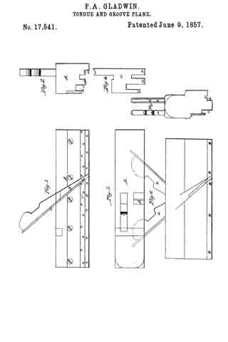
Figure 1, is a side elevation of my improved plane. Fig. 2, a front end view of it. Fig. 3, a top view of it. Fig. 4, a front view of its plane iron or cutter. Fig. 5, is an end view, and Fig. G, a, side view of the ordinary match plane.
The common match plane is made with two separate throats for the reception of separate cutters, which are arranged so as to stand or slant in opposite directions as shown at a, and b, in Fig. 6.
In Fig. 5 c, and d, represent the vertical guides of the tonguing and grooving cutters, their lower edges being arranged on a level with each other while both of such guides are placed between the tonguing and grooving cutters. After the plane has been used to form a tongue it must be turned around or reversed in the hand in order to enable it to make a groove. This is not the case with my improved match plane which always works in one direction whether it be used for cutting a tongue or for making a groove.
In Figs. 1, 2, and 3, A, denotes the stock or body of the plane, which is constructed with a single throat, B, for the reception of a cutter, or plane iron C, formed as shown in front view in Fig. 4, that is, with a grooving cutting edge, i, and tonguing cutting edges, k, k, arranged with respect to one another as shown in said figure. This cutter, C, stands or slants in one direction and operates with vertical guides c’, d’, and horizontal guides f’, g’, h’, arranged as shown in Figs. 1 and 2.
In the common match plane, the vertical guides, c, d, (see Fig. 5) are arranged below the horizontal guides, and so that their lower edges may be on a level, whereas in my improved plane, the vertical guides, c’, d’, are arranged so that one of them viz d’ extends below the other, while the horizontal guide, f’, of the tonguing cutter is arranged between the said two guides, c’, d’. This latter arrangement enables the plane to be used with one handle and either for tonguing or grooving, while its handle is grasped by the hand of a workman, it not being necessary to reverse the plane during the performance of those operations.
The advantages of the improved match plane will be apparent.
I do not claim the combination of tonguing and grooving cutters, upright and horizontal guides in one stock, wherein the tonguing and grooving cutters are arranged to slant in opposite directions, but
What I do claim as an improvement in the match plane is,
The tonguing and grooving cutter or cutters in a single throat and to slant in one direction in combination with arranging the vertical guides so that one shall stand below the other, and the horizontal tongue guide be arranged between as specified.
In testimony whereof I have hereunto set my signature.
PORTER A. GLADWIN.
Witnesses:
R. H. EDDY,
F. P. HALE, Jr.