
| PLEASE NOTE: The images presented on this page are of low resolution and, as a result, will not print out very well. If you wish to have higher resolution files then you may purchase them for only $2.95 per patent by using the "Buy Now" button below. All purchases are via PayPal. These files have all been cleaned up and digitally enhanced and are therefore suitable for printing, publication or framing. Each zip package contains all the images below (some packages may contain more), and purchased files can be downloaded immediately. |
UNITED STATES PATENT OFFICE.
_________________
JUSTUS A. TRAUT AND HENRY RICHARDS, OF NEW BRITAIN, CONNECTICUT.
IMPROVEMENT IN BENCH-PLANES.
_________________
Specification forming part of Letters Patent No. 176,152, dated April 18, 1876; application filed December 27, 1875.
_________________
To all whom it may concern:
Be it known that we, JUSTUS A. TRAUT and HENRY RICHARDS, of New Britain, county of Hartford and State of Connecticut, have invented a certain new and useful Improvement in Bench-Planes; and to enable others skilled in the art to make and use the same, we will proceed to describe it, referring to the drawings, in which the saine letters indicate like parts in each of the figures.
The nature of this invention consists in the device for holding and adjusting the cutting-iron.
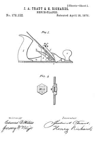
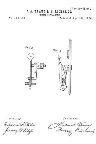
In the accompanying drawings, Figure 1 is a side view of a plane, having one side portion of the stock removed to show the incline brackets, upon which the cutting-iron is held, and the compound levers for adjusting the irons. Fig. 2 is a top view of the compound levers detached from the stock. Fig. 3 is a side view of the compound levers detached from the stock. Fig. 4 is an enlarged view of the adjustable stud by means of which the cut of the iron is regulated through the mouth of the plane by means of the compound levers and the rocking spindle.
The object of this invention is to cheapen the manufacture, and produce a simple, sure, and effective mode of adjusting and holding the irons in the desired condition.
a is the stock. b is the handle; c, the knob for steadying the plane. S is a fastening-pad, which bears upon the lower end or face of the iron, and takes bearings on the upper side against the pins t t, and is provided with a thumb-screw, u, by means of which the iron, when adjusted, is held firmly in place. This fastening-pad and all above described are now in common use. d represents inclined brackets, arranged a short distance apart each way from the center of the stock, and in diverging lines back from the mouth e of the plane, and form bearings for the cutting-irons. f is a rocking spindle, having a groove, g, and a lever, h. This rocking spindle with its lever it is secured by fulcrum-bearings between and near the upper end of the brackets d, while the wrist-pin i in the lower end of the lever h vibrates in an opening in one of the brackets d. j is a thumb-lever, having near its lower end an opening to receive the pin i, which is secured near the lower end of one of the brackets d by a screw, m, and with or without a friction-collar, m’, so that by raising or depressing the lever j by a thumb-pad, n, the required vibration or rotation of the rocking spindle having the groove g will be produced, to cause the movement of the iron up or down. o is a stud, having a tooth projection, o’, fitted to, and working in, the groove of the rocking spindle f This stud o is fitted to play in an opening, p, formed in the cutting-iron or cap-plate, so as to allow it to be adjusted to its proper position, and then secured by a nut, r. Thus it will be seen that by the use of the adjustable stud o its tooth can be readily adjusted, and firmly secured to a single or double iron from time to time, as it becomes worn or ground off from its cutting end, and when the tooth o’ is placed in the groove g of the rocking spindle f by the action of the compound levers h j up and down, the cutting-iron can be easily and accurately adjusted and firmly secured by the fastening-pad S in the common way.
What we claim, and desire to secure by Letters Patent, is —
The combination of the levers h j, rocking spindle f, having groove g and brackets d, with the stud o, having the tooth projection o’, substantially as shown and described.
JUSTUS A. TRAUT. [L. S.] HENRY RICHARDS. [L. S.]
Witnesses:
EDWARD B. WILDER,
JEREMY W. BLISS.