
| PLEASE NOTE: The images presented on this page are of low resolution and, as a result, will not print out very well. If you wish to have higher resolution files then you may purchase them for only $2.95 per patent by using the "Buy Now" button below. All purchases are via PayPal. These files have all been cleaned up and digitally enhanced and are therefore suitable for printing, publication or framing. Each zip package contains all the images below (some packages may contain more), and purchased files can be downloaded immediately. |
UNITED STATES PATENT OFFICE.
_________________
THOS. D. WORRALL, OF LOWELL, MASSACHUSETTS.
METHOD OF ATTACHING ADJUSTABLE HANDLES TO JOINERS’ PLANES.
_________________
Specification of Letters Patent No. 18,312, dated September 29, 1857.
_________________
To all whom it may concern:
Be it known that I, THOS. D. WORRALL, of Lowell, Massachusetts, have invented certain new and useful Improvements in Movable and Adjustable Handles for Molding-Planes; and I do hereby declare that the following is a full, clear, and exact description of the same, reference being had to the accompanying drawings and to the letters of reference marked thereon.
The nature of my invention consists in certain devices for attaching and adjusting the handles on molding planes, the peculiarities of which will be hereinafter described.
In order that others skilled in the art may manufacture and use my invention I will proceed to describe its construction and operation.
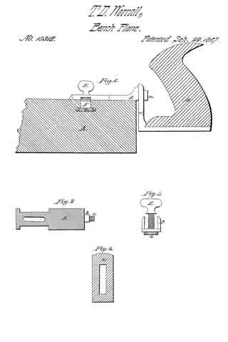
In the accompanying drawings which make a part of this specification Figure 1 is a side elevation. Fig. 2 is a plan view of plate, D, Fig. 1. Fig. 3 is a view showing the slotted face of rectangular strap C. Fig. 4 is view of the nut, button and screw, for attaching plate D to the stock or wood part of the plane.
In Fig. 1 A is the stock or body of the plane, (B), is the handle, (D), is a slotted cap plate, resting on the top of the plane as seen in this figure. (C), is a rectangular strap of metal, the handle (D), being attached to one arm, the other extending several inches in front of the handle, is slotted, as seen in Fig. 4. (F), is a nut, with jaws as seen in Fig. 3. (G), is a button on the back of nut (F). (E), is a thumb screw passing through plate (D), and entering nut (F) as seen in Fig. 3.
Fig. 2 represents the slotted plate (D), (B), is a square shaft, passing through slot in strap C, (c), is a screw on the end of shaft b. Nut (a) in Fig. 1 passes over this screw and attaches plate (D), to strap (C).
In attaching this handle to planes, I first cut a groove in the top of the plane and a mortise in the side, the groove and mortise meeting form a T-shaped slot. The nut, F, fits in the body of this slot and the flanges formed by the projecting of the button beyond the sides of the nut fit in the arms of the slot. Plate D fits on top of the plane, between the arms, or jaws of nut, F, and over the slot, screw, E, passes through the slot in cap plate, D, and enters the nut, F, and secures the handle firmly to the plane. By means of the slot in cap plate D, the handle may be made to assume the position seen in Fig. 1 or strap, C, may lit up snugly against the plane as is the general manner of using it.
Strap C it will be seen is slotted for the purpose of adjusting the handle, elevating or lowering it as circumstances or convenience may require; the handle when placed at any desired position may be secured by means of the nut, (a). This adaptation of the handle to the top or bottom of the plane is particularly desirable in some instances. If the bit is set for cutting a very thin shaving the handle may be at the top or above the top of the plane, but if set for cutting a heavy shaving the handle should be as low as possible in order to have the power in a line with the work, so that the plane will not tilt but move steadily.
One of the chief advantages of my movable handle is that it does away with the necessity of making handle to my planes. They may thereby be aiforded at a much cheaper rate. This handle is so easily adjusted on the plane that but little time will be consumed in changing from one to the other.
Having thus fully described my invention what I claim as new and desire to secure by Letters Patent is —
1. I claim the combination and arrangement of cap plate D, screw E, nut F, and T slot o, in the plane for the purpose of providing and securing a movable handle to planes.
2. I claim the arrangement of cap plate D, slotted strap C, and screw a, for the purpose of adjusting the handle vertically when desired by the operator as set forth and described.
THOS. D. WORRALL.
Witnesses:
C. M. ALEXANDER,
JOHN S. HOLLINGSHEAD.