
| PLEASE NOTE: The images presented on this page are of low resolution and, as a result, will not print out very well. If you wish to have higher resolution files then you may purchase them for only $2.95 per patent by using the "Buy Now" button below. All purchases are via PayPal. These files have all been cleaned up and digitally enhanced and are therefore suitable for printing, publication or framing. Each zip package contains all the images below (some packages may contain more), and purchased files can be downloaded immediately. |

UNITED STATES PATENT OFFICE.
_________________
LEONARD BAILEY, OF HARTFORD, CONNECTICUT.
IMPROVEMENT IN BENCH-PLANES.
_________________
Specification forming part of Letters Patent No. 185,280, dated December 12, 1876; application filed August 31, 1876.
_________________
To all whom it may concern:
Be it known that I, LEONARD BAILEY, of Hartford, in the county of Hartford and State of Connecticut, have invented an Improvement in Bench-Planes, of which the following is a specification, reference being had to the accompanying drawings, where —
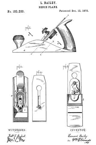
Figure 1 is a side view of a plane bearing my improvements. Fig. 2 is a cross-section on plane x x, looking rearward, as denoted by arrow A, with the plane-irons and fastening cap removed. Fig. 3 is a cross-section on plane y’ y’, looking forward, as denoted by arrow B, with the operating-disk removed. Fig. 4 is a detail view of the rear side of the plane-irons.
The invention is an apparatus or attachment for moving the iron or chisel up and down within limits — that is, for adjusting the chisel.
The letter a denotes the body of an iron plane; b, the bed for the chisel, to the back of which, by screw c, is fastened the bed-elongation d. On shaft-pin e, which projects from the back side of elongation d, is hung, rotarily, the operating-disk f, by which I mean, the disk operated by the user in order to adjust the chisel. On the same shaft-pin, and rigid with the disk f is hung the pinion g, meshing into the gear-segment h, hung on the pin i, projecting from the back of elongation d. In groove i, made in the front side of elongation d, lies and travels the slide k, and a pin, l, projecting rigidly from its back, runs through the mortise m in elongation d, and through the slot n in gear-segment h.
The head of screw o, which holds the two chisels together, lies in the round hole at the lower end of slide k, so that, when the chisels are in place, they and the slide must move together. By rotating the disk f one way or the other, the pinion g and gear segment h are correspondingly rotated, and the pin l, and with it the slide k and irons or chisels, moved up or down correspondingly. When adjusted, the chisels are held to plane in a common manner by means of fastening-cap p and screw v.
I claim as my invention —
1. In combination, bed-elongation d, disk and pinion f g, gear-segment h, and pin l, all substantially as and for the purpose set forth.
2. In combination, disk and pinion f g, gear-segment h, and slide k, all substantially as and for the purpose set forth.
LEONARD BAILEY.
Witnesses:
M. F. DOOLEY,
ROBT. F. GAYLORD.