
| PLEASE NOTE: The images presented on this page are of low resolution and, as a result, will not print out very well. If you wish to have higher resolution files then you may purchase them for only $2.95 per patent by using the "Buy Now" button below. All purchases are via PayPal. These files have all been cleaned up and digitally enhanced and are therefore suitable for printing, publication or framing. Each zip package contains all the images below (some packages may contain more), and purchased files can be downloaded immediately. |
UNITED STATES PATENT OFFICE.
_________________
S. G. CRANE, OF ROCHESTER, NEW YORK.
CROZING-PLANE.
_________________
Specification of Letters Patent No. 19,130, dated January 19, 1858.
_________________
To all whom it may concern:
Be it known that I, S. G. CRANE, of Rochester, in the county of Monroe and State of New York, have invented a new and useful Improvement in Crozing-Planes for Coopers; and I do hereby declare that the following is a full and exact description thereof, reference being had to the accompanying drawings and to the letters of reference marked thereon.
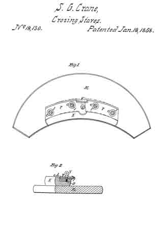
Figure 1, is a plan of the instrument.
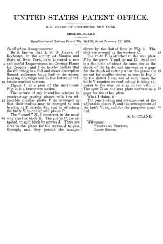
Fig. 2, is a transverse section.
The nature of my invention consists in constructing crozing planes with two adjustable circular plates P so arranged as that their radius may be changed to suit barrels, half barrels, &c., and in attaching the knife V to one of said plates P.
The “board” M, I construct in the usual way also the block K. The plates P, are attached to said block by screws J. There are slots in the plates for the screws J to pass through, and they permit the changes shown by the dotted lines in Fig. 1. The slots are covered by the Washers C.
The knife V is attached to the rear plate P by the screw Y and its nut D. Said nut is a flat plate of about the same size as the shank of the knife, and answers as a gage for the depth of cutting when the plates are set out for smaller circles, as seen in Fig. 1 by the dotted lines, and at such times the knife V requires no readjusting, it being adjusted to the rear plate, is moved with it.
The spur B on the rear plate answers as a gage for the other plate.
What I claim, is —
The construction and arrangement of the adjustable plates P, and the arrangement of the knife V, as, and for the purposes specified.
S. G. CRANE.
Witnesses:
FERDINAND SEIFRIED,
LOUIS ERNST.