
| PLEASE NOTE: The images presented on this page are of low resolution and, as a result, will not print out very well. If you wish to have higher resolution files then you may purchase them for only $2.95 per patent by using the "Buy Now" button below. All purchases are via PayPal. These files have all been cleaned up and digitally enhanced and are therefore suitable for printing, publication or framing. Each zip package contains all the images below (some packages may contain more), and purchased files can be downloaded immediately. |
UNITED STATES PATENT OFFICE.
_________________
SAMUEL D. SARGENT, OF NEW BRITAIN, CONNECTICUT, ASSIGNOR TO THE STANLEY RULE AND LEVEL COMPANY, OF SAME PLACE.
IMPROVEMENT IN BENCH-PLANES.
_________________
Specification forming part of Letters Patent No. 192,132, dated June 19, 1877; application filed November 4, 1876.
_________________
To all whom it may concern:
Be it known that I, SAMUEL D. SARGENT, of New Britain, in the county of Hartford and State of Connecticut, have invented certain new and useful Improvements in Bench-Planes, of which the following is a specification:
My invention consists, in a device for adjusting plane-bits, of a link constructed to operate in the manner hereinafter shown and described.
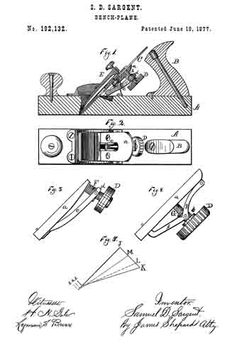
In the accompanying drawing, Figure 1 is a longitudinal section of a bench-plane which embodies my invention. Fig. 2 is a plan view of the same with the cap and plane-irons removed. Figs. 3 and 4 are side elevations, showing diifcrent modifications of the adjusting mechanism for said plane; and Fig. 5 is a diagram to aid in the explanation of my invention.
A designates the stock, and B the handle, both of which may be of any ordinary form and of any suitable material.
The object of my invention is to provide cheap, simple, and eflicient means for adjusting the cutting-bit in its proper position within the stock.
C designates the bit, which may be either a single or double iron, as may be desired. Upon the under side of said bit a series of alternate ribs and channels are formed, as shown in Fig. 1. Upon the under side of the frog a, which frog is the bed upon which the plane iron or bit rests, there is a screw, b, which, in Fig. 1, is a fixed stud threaded externally, and upon it is a larger screw, c, threaded internally to fit the screw b, and externally to fit the nut d, which it carries, the external. thread of the screw c being one banded, and its internal thread and thread of the screw b being threaded in the reverse direction. The larger screw c is also provided with a suitable head, D, or operating-handle.
To the nut d of the screw c one end of a link, e, is secured, and its opposite end lies loosely in a longitudinal slot formed in the frog a, as shown in Fig. 2. This lower end of the link e has a thin projection, which projects a little above the face of the frog, and engages in one of the grooves or channels formed in the under side of the bit, and it is necessary that the link at this end shall rest on ways or other support, so that said end cannot disengage from the plane-bit. The link between its two ends must be clear of all bearings, so as to allow of its free movement. The ordinary holding-cap E, or other proper means, holds the bit in place.
By turning the screw c in one direction the nut d is forced toward the frog a, carrying with it that end of the link e, and, as said link cannot change its length, it follows that the lower end, which is engaged with the cutting-bit, must move downward in the slot in the frog a, and, being so engaged. it must also force the cutting-bit downward with it. By turning the screw in the opposite direction the bit is drawn upward.
The link, for convenience’ sake, is made crooked; but its operation is the same, so long as it is sufficiently rigid, as if it was formed on a straight line between its ends — that is, from the point at which it is secured to the nut to its projecting point at the time of the frog. The operation of this link is, perhaps, more clearly illustrated by reference to the diagram, Fig. 5. The screw, the frog, and the link together form a triangle. In Fig. 5 the side J K is the base of the triangle, and represents the axial line of the screw; the side J 1 the perpendicular, and represents the face line of
the frog, and the side K 1 the hypotenuse, and represents the axial line of the link.
ln the adjustment of the plane iron with this triangular mechanism the link or hypotenuse of the triangle is made to change its position; but it is so confined that its two ends will always be one on the base-line, and the other on the perpendicular-Iine, of a triangle. Three different positions of the link are represented in Fig. 5 — the first by the solid line K 1, the second by the broken line L 2, and the third by the dotted line M 3 — by which it will be seen that, as one end of the hypotenuse is changed in such direction as to shorten the base, the vertex of the vertical angle is carried away from the base. In the diagram the vertex of the vertical angle is changed about one-eighth of an inch for every change there represented. A link engaging with a plane-bit, and changing its position in like manner, would move said bit one-eighth of an inch for every such change.
In Fig. 1 there is a compound screw, hereinbefore described. Its object is to get all the advantage of a fine-threaded screw and the speed of a coarse-threaded one. Such compound screw moves the nut fd just twice as far as it would be moved by it single screw having the same number of threads to an inch, whereby a less number of revolutions of the screw are required in order to effect the desired adjustment than with a single screw.
In Fig. 3 a single screw, F, is shown; but the link and nut are the same as those shown in Fig. 1. The screw is also set at an oblique angle to the face of the frog, in which position the movement of the nut endwise on the screw gives a greater range of motion to the lower end of the link than it would otherwise have.
In Fig. 4 two links, f g, are employed, and jointed together at their meeting ends. The link g is confined to the frog at one end to prevent longitudinal movement. An arm or extension at one end of the link f rests in at grooved nut, h, working on the screw G, and the opposite end of said link f plays loosely in a slot in the frog, as before described for the link e, the object of the additional link g in said rnodification being merely to give a little more throw to the adjustment.
In all of the modifications and mechanisms herein described the link e is employed and arranged to operate substantially the same.
I claim as my invention —
In a device for adjusting plane-bits, the link e, constructed to operate substantially as shown and described, for the purpose set forth.
SAMUEL D. SARGENT.
Witnesses:
FRED. N. STANLEY,
T. A. CONKLIN.