
| PLEASE NOTE: The images presented on this page are of low resolution and, as a result, will not print out very well. If you wish to have higher resolution files then you may purchase them for only $2.95 per patent by using the "Buy Now" button below. All purchases are via PayPal. These files have all been cleaned up and digitally enhanced and are therefore suitable for printing, publication or framing. Each zip package contains all the images below (some packages may contain more), and purchased files can be downloaded immediately. |
UNITED STATES PATENT OFFICE.
_________________
P. A. GLADWIN, OF BOSTON, MASSACHUSETTS.
METHOD OF SECURING THE PLANE-IRON TO ITS STOCK.
_________________
Specification of Letters Patent No. 19,359, dated February 16, 1858.
_________________
To all whom it may concern:
Be it known that I, P. A. GLADWIN, of Boston, in the county of Suffolk and State of Massachusetts, have invented a new and useful Improvement in Joiners’ Planes; and I do hereby declare that the following is a full, clear, and exact description of the same, reference being had to the annexed drawings, making a part of this specification, in which —
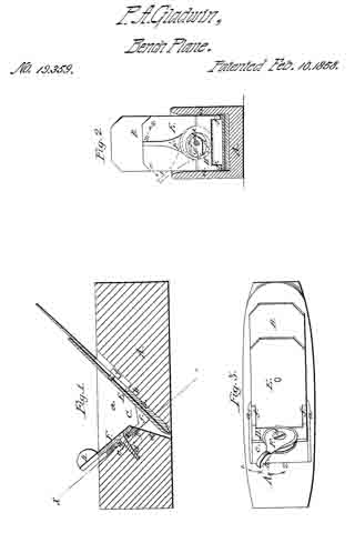
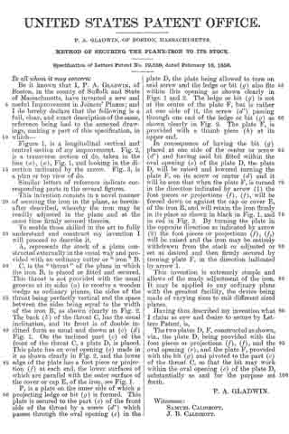
Figure 1, is a longitudinal vertical and central section of my iinproveinent. Fig. 2, is a transverse section of do, taken in the line (x), (x), Fig. 1, and looking in the direction indicated by the arrow. Fig. 3, is a plan or top view of do.
Similar letters of reference indicate corresponding parts in the several figures.
This invention consists in a novel manner of securing the iron in the plane, as hereinafter described, whereby the iron may be readily adjusted in the plane and at the same time firmly secured therein.
To enable those skilled in the art to fully understand and construct my invention I will proceed to describe it.
A, represents the stock of a plane constructed externally in the usual way and provided with an ordinary cutter or “iron” B.
C, is the “throat” of the plane in which the iron B, is placed or fitted and secured. This throat is not provided with the usual grooves at its sides (a) to receive a wooden wedge as ordinary planes, the sides of the throat being perfectly vertical and the space between the sides being equal to the width of the iron B, as shown clearly in Fig. 2. The back (b) of the throat C, has the usual inclination, and its front is of double inclined form as usual and shown at (c) (d) Fig. 1. On the inclined part (c) of the front of the throat C, a plate D, is placed. This plate has an oval opening (e) made in it as shown clearly in Fig. 2, and the lower edge of the plate has a foot piece or projection (f) at each end, the lower surfaces of which are parallel with the outer surface of the cover or cap E, of the iron, see Fig. 1.
F, is a plate on the inner side of which a projecting ledge or bit (g) is formed. This plate is secured to the part (c) of the front side of the throat by a screw (d’) which passes through the oval opening (e) in the plate D, the plate being allowed to turn on said screw and the ledge or bit (g) also fits within this opening as shown clearly in Figs. 1 and 2. The ledge or bit (g) is not at the center of the plate F, but is rather at one side of it, the screw (d’) passing through one end of the ledge or bit (g) as shown clearly in Fig. 2. The plate F, is provided with a thumb piece (h) at its upper end.
In consequence of having the bit (g) placed at one side of the center or screw (d’) and having said bit fitted within the oval opening (e) of the plate D, the plate D, will be raised and lowered turning the plate F, on its screw or center (d and it will be seen that when the plate F, is turned in the direction indicated by arrow (1) the foot pieces or projections (f), (f), will be forced down or against the cap or cover E, of the iron B, and will retain the iron firmly in its place as shown in black in Fig. 1, and in red in Fig. 2. By turning the plate in the opposite direction as indicated by arrow (2) the foot pieces or projections (f), (f) will be raised and the iron may be entirely withdrawn from the stock or adjusted or set as desired and then firmly secured by turning plate F, in the direction indicated by arrow 1.
This invention is extremely simple and allows of the ready adjustment of the iron.
It may be applied to any ordinary plane with the greatest facility, the device being made of varying sizes to suit different sized planes.
Having thus described my invention what I claim as new and desire to secure by Letters Patent, is,
The two plates D, F, constructed as shown, viz., the plate D, being provided with the foot pieces or projections (f), (f), and the oval opening (e), and the plate F, provided with the bit (g) and pivoted to the part (c) of the throat C, so that the bit may work within the oval opening (e) of the plate D, substantially as and for the purpose set forth.
P. A. GLADWIN.
Witnesses:
SAMUEL CALDIROTT,
J. B. CALDIROTT.